
Summary
Virtual Points let GibbsCAM 2024 and later reference useful locations—such as endpoints, midpoints, circle or arc centers and quadrants, solid vertices, and stock corners—without first creating permanent geometry. Use them to place dimensions, interrogate values into dialog or process fields, and define move or rotate references directly from visible geometry, solids, stock, or toolpath.
Table of Contents
Before You Begin
Use GibbsCAM 2024 or later. Earlier releases do not include Virtual Points.
Open the part and activate the intended workgroup and coordinate system before reading or applying a location.
Display the geometry, solid, stock, or toolpath that contains the reference feature. Zoom in and orient the view so nearby candidates can be distinguished.
For a solid model with no extracted geometry, enable edge selection on the Transparent toolbar when you need virtual points from solid edges.
Important: Virtual Points are temporary reference locations; they do not create persistent point geometry. If an operation requires selectable geometry that remains in the part, create an actual point or extract the required geometry.
Procedure
Step 1 - Enable Virtual Points
Open the View menu.
Under the visibility commands, select Virtual Points so the option is active.
For frequent use, add Virtual Points to a toolbar through Customize Toolbars and Menus. The toolbar command toggles the complete Virtual Points display on or off.
Note: Menu placement and shortcut assignments can vary by GibbsCAM release and interface configuration. Use the named Virtual Points command when the displayed shortcut differs.
Step 2 - Reveal the Available References
Open the command that will use the location, or open the Dimension palette and choose the required dimension tool.
Hold Alt and move the pointer near the target geometry, model edge, stock, or toolpath.
Pause over the intended marker. Virtual Points appear only while the pointer is near an available reference and disappear as the pointer moves away.
Confirm the correct marker before selecting it. Depending on the feature, candidates can include endpoints, midpoints, centers, quadrants, radii centers, solid vertices, stock corners or edge points, and similar inferred locations.
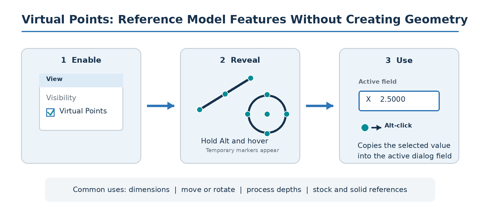
Figure 1 - Enable, reveal, and use a Virtual Point.
Step 3 - Create a Dimension Without Reference Geometry
Open the Dimension palette and select the required coordinate, distance, radius, angle, or other dimension tool.
Move the pointer near the first model feature until its virtual marker appears, then select the marker as the dimension reference.
When the dimension requires another reference, repeat the selection on the second feature.
Place and review the dimension. The dimension can remain without leaving extracted circles, lines, or point geometry in the workgroup.
Step 4 - Interrogate a Value Into an Active Field
Open a Modify command, geometry dialog, process dialog, or other GibbsCAM dialog that contains the value to define.
Click the target text box so the insertion cursor is active in that field.
Hold Alt, move near the required feature, and Alt-click the desired Virtual Point. GibbsCAM copies the interrogated value into the active text box.
Where supported, use Alt+Shift-click to copy the point into multiple coordinate fields at once.
Review the copied coordinate, distance, depth, or angle, then complete the command normally. For example, the Move Part Origin command applies the entered incremental values to all geometry in every workgroup when Do It is selected.
Step 5 - Reference Solid-Model Edges
If no extracted geometry exists in the active workgroup, turn on edge selection from the Transparent toolbar.
Hold Alt and hover near the visible solid edge.
Select the required endpoint, center, quadrant, radius-center, or other available marker for the active dimension or dialog.
Turn edge selection off again when it is no longer needed so normal solid selection is not affected.
Step 6 - Verify and Manage the Display
Confirm that the resulting value or dimension matches the intended feature and the active coordinate system and units.
If the value changed a part, stock, geometry, or process setting, regenerate affected operations and inspect the toolpath.
Run the appropriate operation or machine simulation before posting any affected production operation.
Return to View > Virtual Points and turn the display off when the temporary markers create visual clutter.
Expected Result
GibbsCAM displays temporary reference markers near eligible features. The selected Virtual Point drives the dimension or supplies the active field with the intended value, without adding unnecessary point, line, or circle geometry to the workgroup.
Related Video
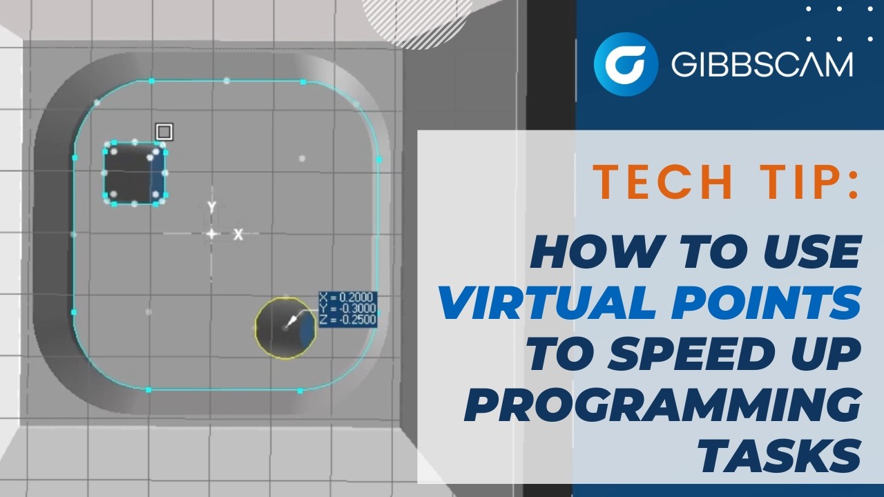
Additional Information
Virtual Points were introduced in GibbsCAM 2024 to support direct dimensioning and interrogation from 3D models without extra reference geometry.
Supported locations include line, arc, and spline endpoints; line midpoints; circle and arc centers; circle quadrants; solid vertices; cubic-stock corners and edge points; and many other feature-dependent references.
Virtual Points can also be used when interrogating visible toolpath and in process parameters such as depth values when the destination field accepts the interrogated value.
Interrogation reads the selected location into a field; it does not automatically verify that the result is appropriate for the active command, coordinate system, machine setup, or posted output.
Troubleshooting
Problem: No Virtual Points appear when Alt is held.
Possible Causes
The Virtual Points visibility command is turned off.
The required geometry, solid, stock, or toolpath is hidden or outside the active view.
The pointer is not close enough to an eligible feature, or the GibbsCAM release predates version 2024.
Edge selection is off while attempting to reference a solid model that has no extracted geometry.
Resolution
Turn on View > Virtual Points, show the source object, zoom in, and hover close to the feature while holding Alt. For solid-model edges without extracted geometry, enable edge selection on the Transparent toolbar. Confirm GibbsCAM 2024 or later is installed.
Problem: Alt-click does not enter a value into the dialog.
Possible Causes
The intended text box is not active.
The pointer selected the model or geometry instead of the temporary marker.
The active control does not support point interrogation or requires a different type of value.
Resolution
Click inside the destination field first, then hold Alt and click the marker itself. If the field does not accept interrogation, read the needed coordinate with a supported dialog or create persistent point geometry and enter the verified value manually.
Problem: The wrong Virtual Point is selected in a crowded area.
Possible Causes
Several endpoints, centers, quadrants, or edges are within the pointer's selection range.
The current view makes separate features overlap on screen.
Too many visibility or selection modes are active.
Resolution
Cancel the selection, zoom closer, rotate to a clearer view, and hide unrelated objects or workgroups. Re-enable only the needed selection mode, hold Alt, and pause over the intended marker before selecting it.
Problem: A moved or edited model gives an unexpected coordinate or stale-looking marker.
Possible Causes
The wrong coordinate system or workgroup is active.
The display has not refreshed after a model, geometry, or workgroup change.
The copied value was interpreted as incremental when the command expected a different reference.
Resolution
Cancel the command, confirm the active workgroup, coordinate system, units, and command semantics. Toggle Virtual Points off and on or refresh the view, then interrogate the feature again. Verify the value before applying any move, rotate, stock, or process change.
Related Articles
- How to Import CAD Files and CAD Compatibilities
- Solid Model Looks Distorted
- How to Set Fixture Avoidance
- How to Save Settings in GibbsCAM
Explore More from CAMCO
Visit the CAMCO website to learn more about:
Keywords
Virtual Points, GibbsCAM 2024, Alt-Click, Interrogate, Dimension Palette, Model Edge, Circle Center, Quadrant Point, Line Midpoint, Solid Vertex, Stock Corner, Edge Selection, Move Part Origin