
Summary
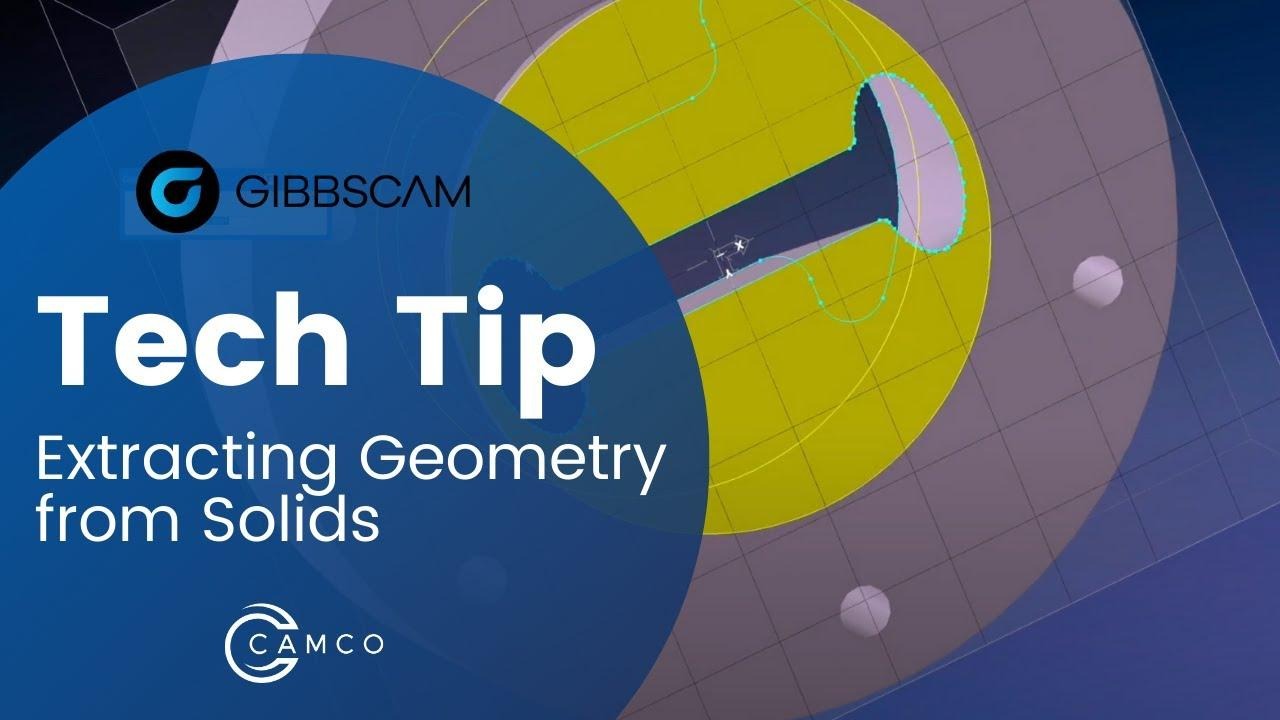
GibbsCAM can extract points, lines, arcs, and curves from a solid model. The resulting geometry can be used for toolpath selection, measurement, construction, or solid-modeling work when direct wireframe control is preferred.
The basic Extract Edges utility can create geometry from an entire body or from selected faces and edges. The available selection methods and advanced extraction tools depend on the installed GibbsCAM options and software version.
Before You Begin
Open or import the solid model and confirm that it is positioned in the intended coordinate system.
Verify that the GibbsCAM license includes Solids Import. The basic geometry-extraction utility is included with this option.
Choose the active workgroup where the extracted geometry should be organized.
Save the part before extracting a large number of edges so the original state is easy to restore.
Note: Advanced extraction methods that use the Profiler require the 2.5D Solids or SolidSurfacer (3D Mill) option. This procedure covers the basic utility available with Solids Import.
Choose the Extraction Scope
Entire body: Use body selection when geometry is needed from the complete solid. This can create a large amount of geometry on a complex model.
Selected faces: Turn on Face Selection and select only the faces whose boundary edges are required.
Selected edges: When the active GibbsCAM version and selection mode permit edge selection, select only the solid edges needed for the workflow.
Procedure
Step 1 - Select the Solid Features
Display the solid body in the GibbsCAM workspace.
Set the solid-selection mode for the required scope: body, face, or edge.
Select the body, faces, or edges from which geometry will be created.
Confirm that only the intended solid features are highlighted before continuing.
Step 2 - Extract the Geometry
Right-click the selected solid feature.
Select Extract Edges from the shortcut menu.
In the Geometry Extraction dialog, review the extraction tolerance.
Tolerance guidance: The tolerance controls the allowable deviation when GibbsCAM converts solid edges into geometry. A tighter value follows the source edge more closely but may produce more complex or fragmented curves. A practical nonzero value may produce cleaner lines and arcs on some imported models. Verify the result before using it for machining.
Click Do It.
Expected Result
GibbsCAM creates geometry corresponding to the selected solid edges in the active workspace.
Step 3 - Inspect and Use the Extracted Geometry
Deselect or temporarily hide the solid so the new geometry is easy to inspect.
Rotate and zoom the view to check the extracted points, lines, arcs, and curves.
Check endpoints and chain selection wherever the geometry will define a closed profile or toolpath boundary.
Delete unwanted or duplicate entities, or undo and repeat the extraction with a narrower selection or different tolerance.
Select the verified geometry in the required machining or modeling operation, then regenerate and inspect the result.
Expected Result
The required solid edges are represented by usable GibbsCAM geometry. The extracted entities can be selected independently for toolpath control, measurement, construction, or modeling, and the resulting operation follows the intended profile.
Why Use Extracted Geometry
Define a machining boundary or chain with direct control over the selected entities.
Create construction geometry or reference locations from an imported solid model.
Measure or inspect features using wireframe entities and endpoints.
Use a combination of geometry, surfaces, and solids to obtain the required toolpath behavior.
Video Tutorial
Best Practices
Extract only the faces or edges required for the task to avoid unnecessary geometry.
Place extracted geometry in a dedicated workgroup when it must remain separate from existing construction geometry.
Start with the current or default extraction tolerance, then change it only after inspecting the result.
Verify closed chains, duplicate entities, and small segments before using extracted geometry for toolpath creation.
Recheck or re-extract geometry after the source solid is replaced or modified.
Troubleshooting
Problem: Extract Edges is not available in the shortcut menu.
Possible Causes
A solid body, face, or edge is not selected.
The active selection mode does not match the feature being selected.
The required Solids Import capability is not available on the license.
Resolution
Select the solid feature again using the appropriate body, face, or edge selection mode. If the command is still unavailable, verify the GibbsCAM license options.
Problem: Too much or duplicate geometry is created.
Possible Causes
The entire body was selected when only a face or edge was needed.
The same solid features were extracted more than once.
Adjacent selected faces share boundary edges.
Resolution
Undo the extraction or remove the duplicate entities. Repeat the command with a smaller selection, and use a dedicated workgroup to make the new geometry easier to review.
Problem: Extracted arcs or lines become splines or fragmented curves.
Possible Causes
The imported solid represents the source edge as a spline or multiple trimmed curves.
The extraction tolerance is not appropriate for the model scale or topology.
Resolution
Repeat the extraction with a practical nonzero tolerance and compare the result. Use the setting that produces acceptable geometry while remaining within the required machining accuracy.
Problem: The extracted profile will not chain or close.
Possible Causes
The selected faces or edges do not form a continuous boundary.
Small gaps, overlaps, or duplicate entities are present in the extracted geometry.
Resolution
Inspect the endpoints closely, remove duplicates, and repair small gaps or overlaps. If necessary, re-extract the required faces or edges with a different tolerance.
Related Articles
Explore More from CAMCO
Visit the CAMCO website to learn more about:
Keywords
Extract Geometry, Extract Edges, Geometry from Solid, Solid Model, Face Selection, Edge Selection, Geometry Extraction Tolerance, Wireframe Geometry, Points, Lines, Arcs, Curves, Solids Import, Profiler, Toolpath Control