
Summary
This article explains how to capture the completed Cut Part Render condition from a first machining setup and reuse it as a faceted stock body for a second setup. The custom body represents the material that actually remains after Op 1 instead of displaying a new rectangular or cylindrical blank.
The workflow creates a facet body from the rendered result, renames and designates it as stock, then rotates and translates it into the Op 2 workholding position. This produces a clearer, more realistic simulation of subsequent operations and makes setup errors easier to identify before the program reaches the machine.
Table of Contents
- Before You Begin
- Procedure
- Stock Body Roles
- Best Practices
- Video Tutorial
- Troubleshooting
- Related Articles
Before You Begin
Program and verify the operations that create the first-setup finished condition.
Model and position the workholding for each setup, including the Op 2 vise, chuck, jaws, or soft jaws.
Confirm that the stock used for Op 1 is correct and that Cut Part Rendering produces the intended remaining material.
Create or activate the coordinate system used to position the body for Op 2.
Save a working copy of the GibbsCAM part before creating or moving the facet body.
Use GibbsCAM commands and labels that correspond to the installed version; menu placement can vary by release and workspace configuration.
Important: A facet body assigned as stock is primarily a rendering/display stock condition. GibbsCAM 2026 documentation states that facet stock is not used as the stock condition for creating toolpath. Define and verify toolpath stock, part, containment, and material-only settings separately.
Procedure
Step 1 - Render the Completed First Setup
Display the stock, part, fixtures, and operations required for the first setup.
Open Cut Part Rendering and run the Op 1 operations through the condition that will be loaded for Op 2.
Inspect the rendered material from several views. Confirm that the first-setup features are complete and that no unexpected stock remains or has been removed.
Leave Cut Part Rendering at the completed Op 1 condition.
Expected Result
The renderer shows the actual in-process workpiece that should enter the second setup.
Step 2 - Create a Facet Body from the Rendered Condition
Right-click the blue title banner of the Cut Part Render dialog.
Select Create Facet Body from the context menu.
Close Cut Part Rendering. The new transparent facet body appears in the workspace and is listed with the other bodies.
Expected Result
A facet body representing the completed Op 1 cut condition is available in the GibbsCAM workspace.
Step 3 - Name and Designate the Op 2 Stock
Open the facet body's properties from the workspace or Body Bag.
Rename the body with a descriptive setup name, such as Op 2 Stock.
Set the body type to Stock. If the installed version presents a display-only stock choice for facet bodies, use the stock option appropriate for rendering.
Place the body on the intended Body Bag page or stock organization page so it can be shown for Op 2 and hidden when it is not needed.
Expected Result
The rendered body is clearly named, organized, and identified as the stock display for the second setup.
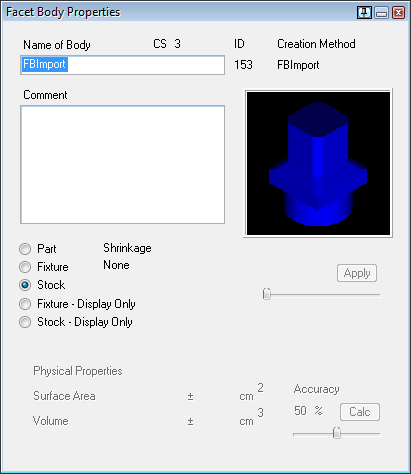
Figure 1 - Facet Body Properties with the Stock body type selected.
Step 4 - Reposition the Stock for the Second Setup
Show the new Op 2 Stock facet body and the workholding used for the second setup.
Activate the coordinate system that makes the required rotation and translation easiest to define.
Rotate or flip the facet body into the physical loading orientation. The video example uses a 90-degree 2D rotation; use the angle required by the actual setup.
Translate the body into the second vise, chuck, or fixture. Use measured model locations or known setup offsets rather than the example dimensions shown in the video.
Inspect the body relative to the jaws, stops, fixture, and Op 2 coordinate system. Correct the orientation or location before proceeding.
Expected Result
The custom stock occupies the same orientation and location as the in-process workpiece when it is loaded for Op 2.
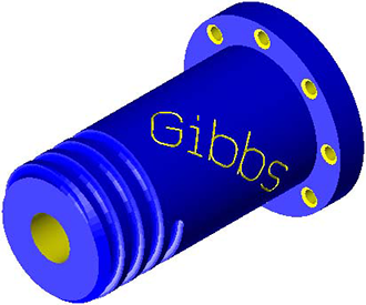
Figure 2 - Example of a completed rendered condition reused as facet stock.
Step 5 - Run and Review the Second-Setup Simulation
Hide or clear stock bodies that do not belong to the second setup, and leave the positioned Op 2 Stock body visible.
Select the Op 2 operations and run Cut Part Rendering or the required simulation mode.
Confirm that the tools begin from the expected remaining-material condition and that the body is seated correctly in the Op 2 workholding.
Review for unwanted air cutting, interference, incorrect setup rotation, missed material, and excessive removal.
Make any required programming or setup corrections, regenerate affected operations, and rerun the complete Op 2 sequence.
Expected Result
The second-setup simulation begins with a realistic representation of the workpiece left by Op 1 and completes without unexpected collisions or stock-removal errors.
Stock Body Roles
Choose the stock definition that matches the job. The facet-body workflow is most useful when a later setup must display the exact shape left by an earlier setup.
Best Practices
Create the facet body only after Op 1 has been regenerated and verified; recreating it is safer than relying on an outdated rendered condition.
Use setup-specific names such as Op 1 Raw Stock and Op 2 Stock, and organize them on separate Body Bag pages when practical.
Position the facet body from known datums, fixture stops, or coordinate-system values instead of dragging it by eye.
Keep the Op 2 fixture visible while positioning the stock, then inspect the setup from several orthographic and Isometric views.
Hide stock and fixture bodies that do not belong to the active setup so the rendered result is unambiguous.
After changes to Op 1, recreate and reposition the facet body before using it to validate Op 2.
Treat simulation as a verification aid. Confirm workholding, offsets, posted output, machine limits, and clearance at the machine before production.
Video Tutorial
Troubleshooting
Problem: Create Facet Body is not available.
Possible Causes
Cut Part Rendering is not open or no rendered cut condition exists.
The context menu was opened from the workspace instead of the Cut Part Render title banner.
The installed GibbsCAM version exposes the command in a different simulation menu.
Resolution
Run the required operations in Cut Part Rendering, stop at the completed Op 1 condition, and open the simulation context menu from the blue title banner. Check the current-version help if the command location differs.
Problem: The facet body was created, but it is not visible after closing rendering.
Possible Causes
The body is hidden or stored on a Body Bag page that is not displayed.
The body is transparent and overlaps the original stock or part.
The view is zoomed away from the body.
Resolution
Locate the facet body in the Body Bag or body list, rename it, show the correct body page, hide overlapping bodies, and fit the view to the workspace.
Problem: Op 2 simulation starts with the wrong stock orientation or location.
Possible Causes
The body was rotated in the wrong coordinate system or about the wrong point.
The translation used visual placement instead of a known setup datum.
The Op 2 fixture or coordinate system is not active or correctly positioned.
Resolution
Undo or restore the saved part, activate the intended coordinate system, and reposition the facet body from known datums or setup offsets. Verify its seating in multiple views before rerunning simulation.
Problem: The custom stock is visible in rendering, but regenerating toolpath does not follow it.
Possible Causes
Facet stock is being used as a display stock condition, not as the stock definition for toolpath creation.
The operation's part, stock, containment, or material-only inputs are defined elsewhere.
Resolution
Define the operation's machining inputs with supported solid, geometry, stock, and process controls. Use the facet body to represent the in-process workpiece in simulation, and verify the behavior for the installed GibbsCAM version.
Problem: The Op 2 stock no longer matches the completed Op 1 toolpath.
Possible Causes
Op 1 was edited or regenerated after the facet body was created.
Only part of the first-setup operation sequence was rendered before capture.
Resolution
Delete or archive the outdated facet body, rerun the complete first-setup sequence, create a new facet body, and repeat the verified Op 2 positioning steps.
Additional Information
Create Facet Body converts the current cut rendered condition into a faceted body. Facet bodies can be queried, profiled, sliced, and machined, but the official GibbsCAM 2026 Machine Simulation documentation describes facet bodies assigned as stock as display-only for toolpath stock purposes.
For a nonstandard raw blank that must define stock independently of a rendered operation, use the Stock Wizard for simple rectangular or cylindrical stock, or define geometry-based custom stock from Workgroup Info when the part and machine configuration support that method.
The dimensions shown in the CAMCO video belong to its sample setup. Every production file must use the actual fixture, coordinate-system, and in-process stock locations for that job.
Sources: CAMCO video transcript; GibbsCAM 2026 Machine Simulation documentation; GibbsCAM 2026 Mill documentation.
Related Articles
- Recommended Simulation Settings
- Utilizing STL Models in GibbsCAM
- How to Set Fixture Avoidance
- Solid Model Looks Distorted
Explore More from CAMCO
Visit the CAMCO website to learn more about:
Keywords
GibbsCAM, Custom Stock Body, Facet Body, Faceted Body, Create Facet Body, Cut Part Rendering, Cut Part Render, Op 1, Op 2, Second Operation, In-Process Stock, Simulation Stock, Stock Display, Body Bag, Stock Properties, Machine Simulation