
Summary
This article provides a practical baseline for GibbsCAM Op, Tool, and Machine Simulation. Use responsive settings for routine review, then increase rendering accuracy and enable collision and program-error feedback for final verification. Values must be appropriate for the part units, smallest relevant feature, machine configuration, and shop standards.
Table of Contents
Before You Begin
Regenerate all operations and confirm that the intended operations are active; simulation applies to active operations.
Verify the part, stock, fixtures, tools, holders, offsets, and machine model before relying on simulation results.
Confirm that MDD axis limits and the loaded machine assembly match the physical machine.
Establish shop-approved chord heights, collision tolerances, gouge tolerances, and high-feed limits for both inch and metric jobs.
Important: A clean simulation does not prove that a program is safe when checking, visibility, or model data is incomplete. Always review posted code and follow the shop's prove-out procedure.
Procedure
Step 1 - Open the Simulation Settings
Choose File > Preferences > Display.
Select Edit Op/Tool and Machine Sim Settings.
Configure Op/Tool Simulation and Machine Simulation separately; the two dialogs store separate settings.
You can also right-click the corresponding Simulation control palette and select Settings.
Note: The values in Figure 1 are examples from the GibbsCAM reference documentation, not universal recommendations.
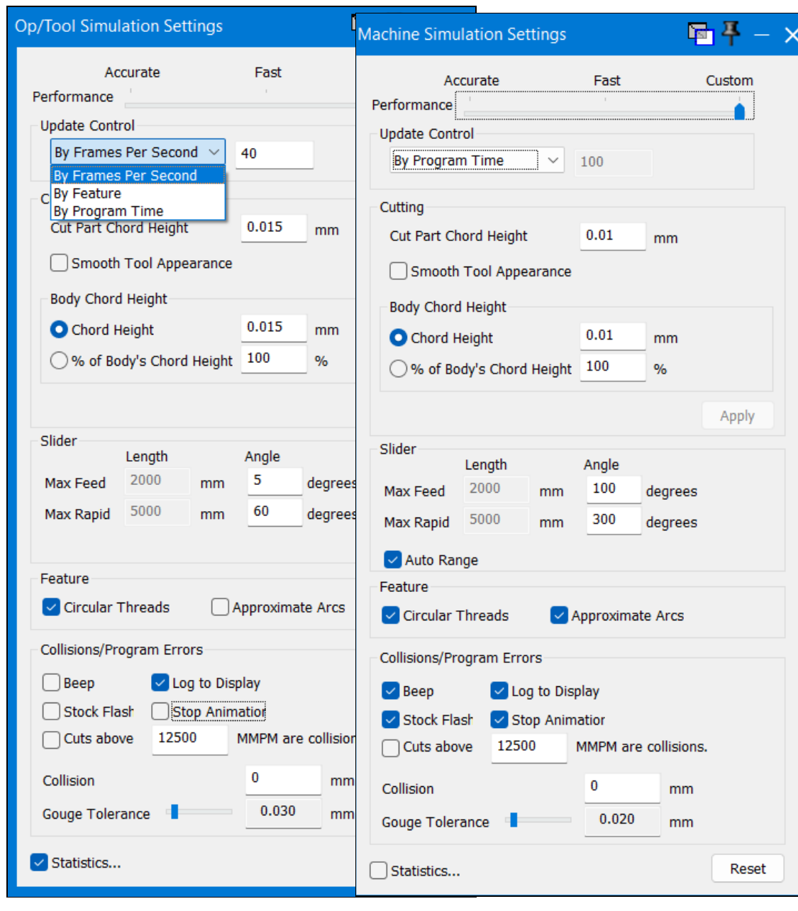
Figure 1 - Op/Tool and Machine Simulation Settings dialogs; example values shown.
Step 2 - Balance Performance and Rendering Accuracy
For routine review, begin with a balanced Performance setting that keeps playback responsive on the current computer.
Choose an Update Control: use By Frames Per Second for smooth playback, By Feature for feature-by-feature review, or By Program Time when approximate machining-time playback is useful.
Set Cut Part Chord Height and Body Chord Height to the shop standard for the job units. Smaller values create a more accurate display but require more processing time.
For final verification, tighten the chord heights enough to resolve the smallest feature or clearance that matters to the setup.
For rotary motion, use smaller Angle increments when a smoother, more detailed rotation is required. In Machine Simulation, enable Auto Range when stock size should determine feed and rapid length ranges.
Use performance shortcuts such as Approximate Arcs only for review when needed; repeat final verification with accuracy settings that do not hide relevant motion or small features.
Step 3 - Configure Collision and Error Feedback
Under Collisions/Program Errors, enable Log To Display, Stock Flash, and Stop Animation. Enable Beep if audible notification is useful in the work area.
To detect unintended high-feed cuts, enable Cuts above [value] are collisions and enter the highest feedrate that the shop permits while the tool is engaged in material.
Set Collision Tolerance to the shop-approved value for the job units. Do not loosen the value merely to suppress a valid collision.
Set Gouge Tolerance no larger than the amount of removed material the shop permits the analysis to ignore.
Enable Statistics when diagnosing performance or when a record of frame rate and logged errors is useful.
Step 4 - Enable the Required Simulation Controls
Use Op Simulation to review material removal and part-centric tool motion. Use Tool Simulation to review toolpath and inter-operation moves, but do not use it as a substitute for collision checking.
Use Machine Simulation for final verification when machine components, rotary motion, tool changes, part transfers, or inter-operation motion are relevant.
Enable Show Tool Holders and Show Rapid Tool. Keep the stock, fixtures, and required machine components visible.
Enable Collision Checking in Op or Machine Simulation and enable Program Error Checking in Rapid, Op, or Machine Simulation as appropriate.
If the job uses duplicated parts, enable Show Multipart so every required part instance and fixture is included in the review.
Use Skip Unselected Ops for focused diagnosis when needed, but complete a full-sequence simulation before release.
Step 5 - Run the Final Verification
Rewind the simulation and run the complete active operation sequence from the beginning.
Inspect cutting, rapid, entry, exit, tool-change, rotary, transfer, and inter-operation moves from more than one viewpoint.
Pause or use Stops around high-risk operations and transitions so small clearances can be reviewed at a slower playback speed.
Review every collision and program-error log entry. Identify the operation, tool or holder, stock or fixture, location, and machine axis involved.
Correct the toolpath, setup, tool or holder data, fixture definition, MDD, or simulation setting responsible for the issue, then regenerate and rerun the complete sequence.
Review the posted program and follow the shop's normal prove-out procedure before machining the part.
Expected Result
Simulation remains responsive during routine review and provides sufficient visual detail during final verification. Tools, holders, stock, fixtures, and required machine components are visible; collision and program-error checks are enabled; all alerts are resolved; and the complete active operation sequence has been reviewed.
Troubleshooting
Problem: Simulation runs, but collisions are not reported.
Possible Causes
Collision Checking is not enabled in the Simulation control palette.
Collision feedback is disabled in the Op/Tool or Machine Simulation Settings dialog.
Tool Simulation is being used even though collision checking is required.
The holder, fixture, stock, or machine component is missing or hidden.
Resolution
Use Op or Machine Simulation, enable Collision Checking, turn on Log To Display and Stop Animation, and confirm that every required body and component is defined and visible.
Problem: The simulated part or motion looks rough, faceted, or unclear.
Possible Causes
Cut Part Chord Height, Body Chord Height, or rotary Angle increments are too coarse for the feature being reviewed.
The Performance slider is set primarily for speed, or a performance shortcut is reducing visual detail.
Resolution
Move the Performance setting toward accuracy, reduce the applicable chord-height or angle values, disable unnecessary approximation, reload the simulation, and review the affected area again.
Problem: Simulation is too slow for practical review.
Possible Causes
Chord heights or rotary Angle increments are tighter than the review requires.
Collision checking, detailed machine components, and all operations are being processed during a focused diagnostic review.
The simulation window or visible model is larger or more detailed than necessary.
Resolution
Use balanced settings for routine review, reduce nonessential display detail, and use Skip Unselected Ops for focused diagnosis. Restore the required accuracy, visibility, collision checking, and full operation sequence for final verification.
Problem: Program Error Checking reports an axis-limit error.
Possible Causes
The programmed motion exceeds a machine-axis limit.
Axis limits, offsets, or kinematics are incorrect in the MDD or machine model.
The wrong machine configuration, tool, holder, or part setup is active.
Resolution
Verify the active machine configuration, part and tool data, offsets, MDD axes, and machine limits. Correct the program or machine definition and rerun the simulation; do not disable limits merely to hide the error.
Related Articles
- Create a Custom Stock Body for More Accurate Simulation
- Solid Models Look Distorted
- How to Set Fixture Avoidance
- Clearance Volumes
Explore More from CAMCO
Visit the CAMCO website to learn more about:
Keywords
Simulation Settings, Op Simulation, Tool Simulation, Machine Simulation, Collision Checking, Program Error Checking, Chord Height, Gouge Tolerance, Collision Tolerance, Tool Holder