
Summary
If a solid model appears faceted, blocky, or distorted in GibbsCAM, the most common cause is the Chord Height setting. Chord Height controls the display accuracy of solid models. A larger value displays fewer polygons for better graphics performance but can make curved surfaces appear flat. A smaller value increases detail but requires more graphics processing.
Before You Begin
Determine whether the issue affects one solid model or all solid models.
Close unnecessary applications when working with large or complex assemblies.
Be aware that decreasing Chord Height may reduce graphics performance on older hardware.
Note: Chord Height affects only the visual representation of a model. It does not change the actual geometry or machining accuracy.
Symptoms
Round surfaces appear flat or faceted.
Cylinders show visible flat edges.
Imported or newly created solids have a coarse or distorted appearance.
Cut Part Rendering appears less detailed than the solid model.
Procedure
Step 1 - Check the Global Chord Height
Select File > Preferences > Display.
Review the current Chord Height value.
If the value is too large, newly imported or created solids will appear with reduced detail.
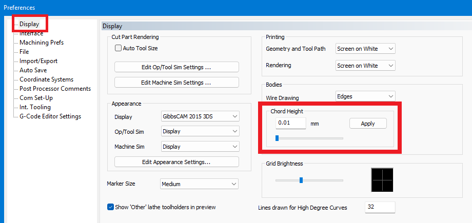
Figure 1 - Global Chord Height in File > Preferences > Display.
Step 2 - Adjust the Global Chord Height
Reduce the Chord Height value to increase display quality.
Select Apply.
Evaluate the model, then make another small adjustment only if more detail is needed.
Tip: Make small adjustments and evaluate the result before reducing the value significantly.
Step 3 - Check the Individual Solid
Each solid model stores its own Chord Height value.
Right-click the solid model.
Select Show Properties.
Review the model's Chord Height setting.
Adjust the value if necessary, select Apply, and regenerate the model when required.
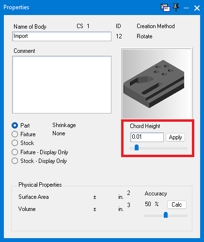
Figure 2 - Chord Height stored in the selected solid model's Properties dialog.
Step 4 - Review Cut Part Rendering
Cut Part Rendering maintains its own independent Chord Height settings.
Open the Machine Simulation or Cut Part Rendering settings used by the current workflow.
Review Cut Part Chord Height and Body Chord Height.
Reduce the appropriate value if the machined Cut Part appears faceted while the solid model looks correct.
Select Apply and reevaluate the rendering.
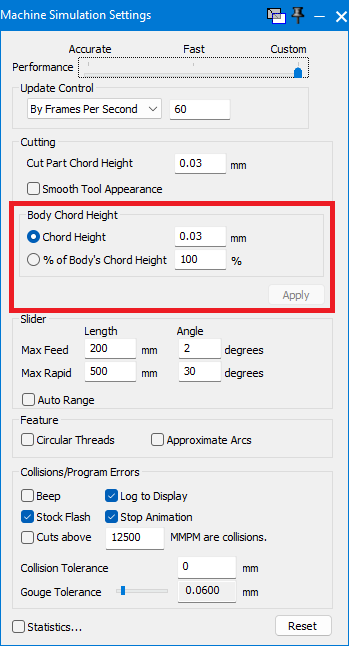
Figure 3 - Independent Chord Height controls in Machine Simulation Settings.
Expected Result
Solid models and Cut Part Rendering display smooth curved surfaces without unnecessary faceting while maintaining acceptable graphics performance.
Additional Information
What Is Chord Height?
GibbsCAM approximates mathematically curved surfaces with many small flat facets for display. Chord Height determines how closely those facets follow the true curve.
Common Causes
The global Chord Height is set too large.
The individual solid model has a coarse Chord Height.
Cut Part Rendering uses a different Chord Height setting.
Graphics settings were adjusted to favor performance over display detail.
Best Practices
Use the smallest Chord Height that provides acceptable workstation performance.
Increase detail only when it is needed for inspection or visualization.
Keep graphics drivers current for optimal rendering performance.
Remember that visual appearance does not affect machining accuracy.
Troubleshooting
Problem: Round surfaces appear flat.
Possible Causes
The Chord Height is set too large.
Resolution
Reduce Chord Height in Display preferences or for the individual solid model, then reevaluate the curved surfaces.
Problem: Imported models appear coarse.
Possible Causes
The global Chord Height used when the model was imported is too large.
Resolution
Right-click the model and select Show Properties to lower the individual Chord Height. Lower the Display Chord Height and reimport the model if necessary.
Problem: The solid model looks correct, but the Cut Part appears faceted.
Possible Causes
Cut Part Rendering uses an independent Chord Height setting.
Resolution
Adjust Cut Part Chord Height or Body Chord Height in the Cut Part Rendering or Machine Simulation settings, then apply the change and rerun the display.
Problem: Reducing Chord Height slows graphics performance.
Possible Causes
Higher display detail requires additional GPU processing and video memory.
Resolution
Increase Chord Height slightly until an acceptable balance between appearance and performance is achieved.
Related Articles
- Troubleshooting Graphical Issues in GibbsCAM
- Contour Trace Not Working
- Troubleshooting GibbsCAM Crashes, Freezes, or Unexpected Closures
- Hardware and System Requirements
- Utilizing STL Models in GibbsCAM
Explore More from CAMCO
Visit the CAMCO website to learn more about:
Keywords
Solid Model, Distorted Model, Chord Height, Display Quality, Faceted Model, Flat Edges, Graphics, Rendering, Cut Part Rendering, Solid Properties