
Summary
Clearance Volumes provide an alternative to a traditional clearance plane for supported advanced-machine configurations. When the selected Machine Definition Database (MDD) implements this behavior, GibbsCAM uses the stock definition and a Clearance (Δ) offset to calculate clearance for interoperation motion. This article explains how to confirm support, set the offset, display the volume, and validate the resulting motion.
Table of Contents
Before You Begin
Use an MDD and post processor that were configured for Clearance Volumes by CAMCO, your GibbsCAM reseller, or the Gibbs Post Department.
Do not change Clearance Volume options in the MDD unless you are authorized and trained to edit machine definitions.
Confirm that the machine control and post configuration support the simultaneous motion required for generated interoperation moves. TCP capability is recommended.
Important: Clearance Volumes are not suitable for machines with indexing rotary axes or rotary axes that must be clamped between moves. They do not replace accurate stock, tool, holder, fixture, offset, simulation, or machine prove-out data.
When to Use Clearance Volumes
Clearance Volumes are most useful when a single CP1 clearance plane cannot provide practical interoperation clearance. Common candidates include multi-axis machines with rotary heads or tables, non-Z-aligned tools, independently rotating tool and part stations, eccentric turning, and tall-part setups where returning to a distant fixed plane creates unnecessary travel.
Procedure
Step 1 - Confirm the MDD Uses Clearance Volumes
Load the GibbsCAM part and select the intended machine definition.
Confirm with CAMCO, your reseller, or the post developer that the selected MDD is configured and tested for Clearance Volumes.
For an authorized MDD review, verify that Clearance Behavior is set to Clearance Volumes. End users should not change this setting themselves.
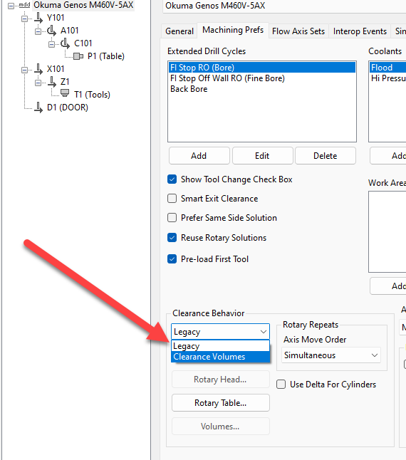
Figure 1. Clearance Volumes selected in an authorized MDD configuration.
Step 2 - Define Stock and Set the Clearance Offset
Open the Document Control Dialog (DCD) and verify that the stock size, location, and part origin match the physical setup.
On the DCD Workspace page, locate Clearance (Δ). This field appears when the selected Mill MDD implements Clearance Volumes.
Enter an incremental offset from the default stock definition that provides adequate clearance for the setup, tools, and holders.
Apply the DCD changes. Do not use the example value as a universal recommendation; the required offset depends on the machine and setup.

Figure 2. The Clearance (Δ) field sets an incremental offset from the stock definition.
Step 3 - Add the Show Clearance Volumes Command
Right-click the top of the GibbsCAM window and select Customize Toolbars & Menus.
Search for Show Clearance Volumes in the customization dialog.
Drag the command onto the required toolbar or menu, then close the customization dialog.
Step 4 - Display and Inspect the Clearance Volume
Select Show Clearance Volumes so the command is on.
Confirm that GibbsCAM displays a clearance volume around the intended stock. If the MDD does not define a clearance volume, the same display command shows the current operation's clearance plane instead.
Rotate the view and inspect the volume from multiple directions. Confirm that the stock definition and delta provide the intended space for each tool orientation.
Note: Clearance Volume calculations are based on the configured stock and machine definition. Validate fixtures separately; see the related fixture-avoidance article.
Step 5 - Validate the Complete Program
Regenerate the affected operations after changing the stock definition or clearance offset.
Run Machine Simulation for the complete program and inspect all entry, exit, interoperation, rotary, tool, holder, stock, and fixture motion.
Confirm that the post processor outputs motion that is compatible with the control's TCP and rotary-axis requirements.
Follow the machine manufacturer's and your organization's prove-out procedures before running the program unattended.
Expected Result
GibbsCAM displays a clearance volume based on the selected MDD, stock definition, and Clearance (Δ) offset. The resulting interoperation motion clears the programmed stock in simulation and is compatible with the verified machine, control, and post configuration.
Additional Information
When Show Clearance Volumes is off, GibbsCAM displays neither clearance volumes nor clearance planes.
When the command is on, GibbsCAM displays the MDD-defined clearance volume; if no volume is defined, it displays the current operation's clearance plane.
Troubleshooting
Problem: The Clearance (Δ) field or Show Clearance Volumes command is not available.
Possible Causes
The selected MDD does not implement Clearance Volumes, or the display command has not been added to the interface.
Resolution
Confirm that the correct MDD is loaded and supports Clearance Volumes. If it does, add Show Clearance Volumes through Customize Toolbars & Menus. Contact CAMCO, your reseller, or the post developer if the MDD requires review.
Problem: The displayed volume is too close to the stock or does not match the setup.
Possible Causes
The stock definition, part origin, offsets, or Clearance (Δ) value is incorrect or too small.
Resolution
Correct the stock and setup data, increase the Clearance (Δ) offset as needed, regenerate the affected operations, and repeat the complete simulation review.
Problem: The generated interoperation motion is not suitable for the machine control.
Possible Causes
The control lacks the required TCP capability, or a rotary axis is indexing-only or must be clamped between moves.
Resolution
Do not run the program. Contact CAMCO, your reseller, or the post developer to select a supported clearance strategy and verify the MDD and post configuration.
Related Articles
- How to Set Fixture Avoidance
- Traversal Options
- Error: "The MDD Selected Does Not Match Your Security Options"
Explore More from CAMCO
Visit the CAMCO website to learn more about:
Keywords
GibbsCAM Clearance Volumes, Clearance Volume, Clearance delta, Clearance Δ, CP1, clearance plane, MDD, interoperation moves, TCP, multi-axis clearance