
Summary
This article recreates the Geometry Creation lesson from CAMCO's GibbsCAM Mill Tutorial. The exercise uses a dimensioned flange print to build the machining geometry as 2D wireframe in the XY plane.
The workflow creates three center points, the three holes, three outer construction circles, four tangent connector arcs, and a 0.125-inch inward offset. The completed geometry is then checked and saved for the next tutorial steps.
Table of Contents
- Before You Begin
- Key Geometry Values
- Procedure
- Best Practices
- Video Tutorial
- Troubleshooting
- Related Articles
Before You Begin
Use a Mill part with a 3-axis vertical-mill setup and work in the Top view (XY plane).
Set the part units to inches for this exercise. If metric units are active, convert every dimension consistently before creating geometry.
Save the part before beginning and use a dedicated workgroup for the tutorial geometry when practical.
Download or open the flange print and keep it visible while entering the dimensions.
Use Z0 for the 2D wireframe geometry created in this lesson.
If the coordinate-system marker hides the point at X0, Y0, temporarily turn the marker off while creating the geometry.
Tutorial print: Download GC-Flange.pdf
Important: The drawing fields in GibbsCAM can evaluate arithmetic. After entering a calculation such as 2.5/2 or 0.625/2, press Tab or the equals key to evaluate it. Avoid pressing Enter while a Do It command is active, because it can execute the command unexpectedly.
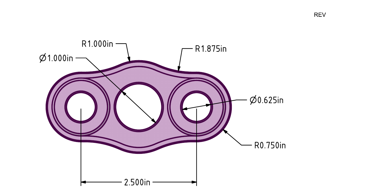
Figure 1 - Top view and dimensions from the CAMCO GC-Flange tutorial print.
Key Geometry Values
Procedure
Step 1 - Review the Print and Prepare the View
Open the flange print and identify the three hole centers, hole diameters, outer radii, tangent connector radius, and inset step.
Open or create the GibbsCAM Mill part and switch to the Top view so X is horizontal and Y is vertical.
Confirm that the active workgroup and coordinate system are correct and that new geometry will be created at Z0.
Turn off the coordinate-system marker if it blocks the origin point during selection.
Step 2 - Create the Three Center Points
Open Geometry > Point > Explicit.
Enter X0, Y0, Z0 and select Do It to create the center point.
Create the right point at X1.250, Y0, Z0. You can enter 2.5/2 and evaluate the field.
Create the left point at X-1.250, Y0, Z0 by changing the sign of the X value.
Confirm that the two side points are 2.500 inches apart and symmetric about the origin.
Expected Result
Three collinear center points appear at X-1.250, X0, and X1.250 on Y0.
Step 3 - Create the Three Holes
Return to the main Geometry palette and choose Circle > Radius & Center Point.
Set the radius to 0.3125, or enter 0.625/2 and evaluate the field.
Ctrl-select the left and right center points, then select Do It to create both 0.625-inch-diameter holes at the same time.
Set the radius to 0.500, select the origin point, and select Do It to create the 1.000-inch center hole.
Expected Result
The wireframe contains two 0.625-inch side holes and one 1.000-inch center hole.
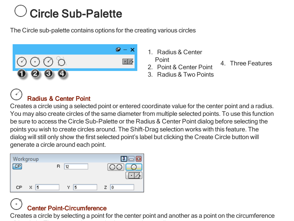
Figure 2 - Circle sub-palette and Radius & Center Point controls.
Step 4 - Create the Three Outer Construction Circles
Choose Circle > Radius & Center Point again.
Set the radius to 1.000, select the origin point, and create the center outer circle.
Change the radius to 0.750, Ctrl-select the left and right center points, and create both side outer circles.
Confirm that the three construction circles overlap as shown on the flange print.
Step 5 - Create and Trim the Tangent Connector Arcs
Ctrl-select the center outer circle and one adjacent side outer circle.
Select the Circle tool. GibbsCAM opens the inferred Circle Tangent to Two Circles function with both selected circles loaded.
Enter a radius of 1.875 and select Do It.
From the available tangency solutions, select the connector circle that forms the required outside arc, then select OK. GibbsCAM trims the connected circles automatically.
Repeat the selection and tangent-circle process for the remaining top and bottom connections, working around the part one connection at a time.
If a trimmed source circle is no longer available for the next connection, select the remaining circle or arc and choose Modify > Duplicate before creating the next tangent solution.
If a retained arc runs in the wrong direction, choose Modify > Reverse Arc or press Ctrl+T.
Expected Result
The outside profile is a connected shape made from the retained portions of the three outer circles and four 1.875-inch tangent connector arcs.
Step 6 - Create the Inner Step with Offset
Double-click one element of the finished outside profile to chain-select the entire connected shape.
Choose Geometry > Shape > Offset.
Set Distance to 0.125 and turn off Square Corners.
Select Do It. GibbsCAM creates an inward and an outward offset copy of the selected shape.
Delete the outside offset and keep the inward offset that represents the step shown on the print.
Expected Result
A second connected profile appears 0.125 inch inside the completed outside shape.
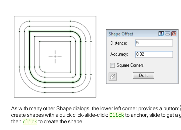
Figure 3 - Shape Offset dialog with Square Corners turned off.
Step 7 - Verify and Save the Geometry
Return to the Top view and compare the three holes, the outside profile, and the inward offset with the flange print.
Double-click the outside and inner profiles separately to verify that each chain selects continuously without gaps or branches.
Switch briefly to the Isometric view and use Unzoom or Ctrl+U to inspect the geometry and any construction points created during tangency calculations.
Return to the Top view, remove only unwanted construction geometry, and save the GibbsCAM part for the next tutorial lesson.
Expected Result
The saved part contains clean 2D wireframe geometry at Z0 that matches the flange print and is ready for tool and process creation.
Expected Result
The GibbsCAM part contains three correctly positioned holes, a fully connected outside flange profile, and a connected 0.125-inch inward offset. The geometry matches the print dimensions, chain-selects correctly, and is saved for the remaining Mill Tutorial lessons.
Best Practices
Create the primary center points first so every circle is referenced from known coordinates.
Enter radii in circle dialogs; divide print diameters by two instead of entering the diameter directly.
Use Ctrl-selection to create identical circles from multiple center points in one command.
Before accepting a tangent-circle solution, confirm that it forms the correct outside arc and trims the intended features.
Duplicate source geometry before another connection when the previous trim removed the circle needed for the next tangent solution.
Chain-select profiles after trimming and offsetting to find gaps, overlaps, branches, or unintended duplicates before machining.
Save incremental versions after the points and holes, the outside profile, and the final offset so a clean stage can be restored quickly.
Video Tutorial
Continue the Tutorial
Part 2: Tool Creation
Part 3: Roughing
Part 4: Finishing
Part 5: Chamfering
Troubleshooting
Problem: The origin point is difficult to see or select.
Possible Causes
The coordinate-system marker is displayed over X0, Y0.
The view is zoomed too far out for the point marker to be clear.
Resolution
Temporarily turn off the coordinate-system marker, switch to the Top view, and use Unzoom or zoom in around the origin. Re-enable the marker after the point is created if it is needed for verification.
Problem: The holes or construction circles are twice the expected size.
Possible Causes
A diameter from the print was entered into a radius field.
The arithmetic expression was not evaluated before Do It was selected.
Resolution
Delete or undo the incorrect circle. Enter 0.3125 for the 0.625-inch holes and 0.500 for the 1.000-inch center hole, or enter diameter/2 and evaluate the field with Tab or equals before selecting Do It.
Problem: A tangent connector creates the wrong arc or removes geometry needed for the next connection.
Possible Causes
The wrong tangency solution was selected.
The two source circles were selected in the wrong area or an unintended feature was included.
Automatic trimming consumed a circle needed for the next connector.
Resolution
Undo the connection, Ctrl-select only the intended pair of outer circles, enter the 1.875 radius, and choose the correct outside solution. Use Modify > Duplicate before the next connection when the required source circle was trimmed away.
Problem: A retained tangent arc is oriented incorrectly.
Possible Causes
The selected solution created the correct arc location but its direction is reversed.
Resolution
Select the affected arc and choose Modify > Reverse Arc, or press Ctrl+T. Recheck the connected chain before continuing.
Problem: The offset is on the wrong side, has square corners, or will not chain.
Possible Causes
The outward offset was retained instead of the inward copy.
Square Corners was selected.
The source outside profile contains a gap, overlap, branch, or duplicate element.
Resolution
Undo or delete the incorrect offset. Repair the outside profile until it chain-selects as one connected shape, set Distance to 0.125, clear Square Corners, create the offsets again, and keep only the inward copy.
Additional Information
GibbsCAM uses inferred geometry functions when the selected features define the required construction. In this lesson, selecting two circles before choosing Circle opens the tangent-to-two-circles function automatically.
The screenshots in this article are from the GibbsCAM 14 Geometry Creation reference. Button artwork and palette placement can differ in newer releases, but the Radius & Center Point, inferred tangent-circle, Reverse Arc, Duplicate, and Shape Offset concepts remain applicable.
Sources: CAMCO GC-Flange print and Geometry Creation video transcript; GibbsCAM 14 Geometry Creation, Working with Geometry.
Related Articles
- Geometry Does Not Connect or Disconnect Properly
- Extracting Geometry from Solids
- Lines Importing as B-Splines
- Importing Images for Toolpath Creation
Explore More from CAMCO
Visit the CAMCO website to learn more about:
Keywords
GibbsCAM, Mill Tutorial, Geometry Creation, 2D Wireframe, Explicit Point, Radius and Center Point, Tangent Circle, Inferred Geometry, Reverse Arc, Duplicate Geometry, Shape Offset, Flange Print, Circle Geometry, Connected Shape, XY Plane