
Summary
This article recreates the Import lesson from CAMCO's GibbsCAM Mill Tutorial from a solid. It shows how to import a Parasolid model and prepare an assembly-derived body for machining in the active GibbsCAM coordinate system.
The workflow aligns a planar face to the coordinate system, translates the machining face to Z0, and corrects any remaining X-Y rotation with extracted geometry and Absolute Rotate. The completed solid is positioned and oriented for tool, process, and operation creation.
Table of Contents
- Before You Begin
- Procedure
- CAD Clock Angle Reference
- Best Practices
- Video Tutorial
- Troubleshooting
- Related Articles
Before You Begin
Start a GibbsCAM Mill part with the intended machine and active coordinate system.
Confirm the part units before importing. The model and GibbsCAM part should use compatible units.
Verify that the required CAD translator and Solids Import capability are available on the GibbsCAM license.
Save the empty or starting part before import so the original setup can be restored easily.
Identify the model face that should be normal to the machining Z axis and the feature direction that should align with X or Y.
Download the tutorial model or use a working copy of your own solid model.
Tutorial model: Download GC-Flange.x_t
Important: Imported models may retain coordinates from a CAD assembly and can appear far from the GibbsCAM origin or rotated relative to the machine axes. This does not necessarily indicate damaged geometry.
Procedure
Step 1 - Download the Model and Prepare the Part
Download GC-Flange.x_t from the tutorial link, or copy the source CAD model to a working folder.
Open GibbsCAM and create or open the Mill part that will receive the solid.
Confirm the active machine, coordinate system, units, and workgroup before importing.
Save the GibbsCAM part with a new name before continuing.
Step 2 - Import the Solid Model
Select File > Import.
Choose the CAD file type. For the tutorial file, select Parasolid (*.x_t or the available Parasolid filter).
Browse to GC-Flange.x_t, select the file, and select Open.
Wait for the translator to finish, then confirm that a solid body appears in the workspace.
Expected Result
The Parasolid body is visible in GibbsCAM, although its position or orientation may still reflect the original CAD assembly.
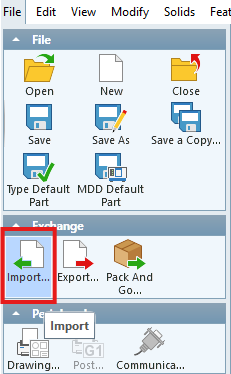
Figure 1 - Import command on the GibbsCAM File palette.
Step 3 - Inspect the Imported Body
Use Unzoom or fit the view so the entire imported body is visible.
Rotate the view and determine whether the body is aligned with the active machine X, Y, and Z axes.
Check whether the intended machining face is at Z0 and whether the body is located near the usable part origin.
If the model is already aligned and positioned correctly, continue to Step 7. Otherwise, complete the alignment steps below.
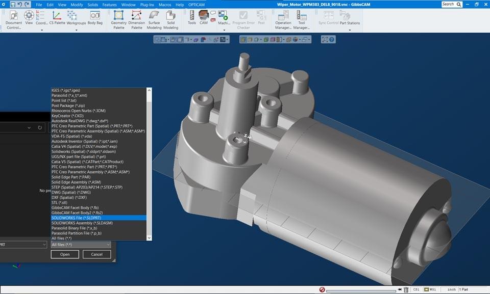
Figure 2 - GibbsCAM solid-import workspace with CAD file types and an imported body.
Step 4 - Align a Primary Face to the Coordinate System
Turn on Face Selection.
Select the planar face that should be aligned to the active coordinate system.
Right-click the selected face and choose Align Face to CS.
Inspect the body from the Top, Front, and Right views to confirm that the selected face is aligned as intended.
Expected Result
The selected planar face is aligned to the active coordinate system. The body may still require translation to Z0 or rotation about the Z axis.
Step 5 - Translate the Machining Face to Z0
Select Modify > Absolute Translate.
Activate the source Z field. Hold Alt and select the machining face to read its current Z height into the field.
Select the solid body that will be moved.
Set the destination Z value to 0. In the tutorial example, the measured source face is at Z0.25, but use the actual value from your model.
Select Do It and verify the new location.
Expected Result
The intended machining face is located at Z0 without changing the solid's shape or size.
Step 6 - Correct Remaining X-Y Rotation When Needed
If the body is still skewed about Z, select faces or circular edges that define the required X or Y direction.
Right-click and choose Extract Edges to create reference geometry from the selected solid features.
Open Geometry > Point > Center Point, select each reference circle, and select Do It to create two center points.
Create a line between the two center points. This line represents the current feature direction.
Select Modify > Absolute Rotate.
Activate the From angle field, hold Alt, and select the reference line to read its current angle.
Set the To angle to the required machine-axis direction, such as 0 degrees for +X or 90 degrees for +Y.
Select the body and any reference geometry that should move with it, then select Do It.
Inspect the result and remove or hide temporary construction geometry when it is no longer required.
Expected Result
The solid is square with the intended X and Y machine directions while the machining face remains at Z0.
Step 7 - Verify and Save the Prepared Solid
Check the solid in the Top, Front, Right, and Isometric views.
Confirm that the machining face is at Z0 and the model is located at the intended part origin.
Verify that the principal features are parallel or perpendicular to the intended machine axes.
Save the GibbsCAM part for the remaining solid-milling tutorial lessons.
Expected Result
The imported body is positioned, oriented, and saved for tool and process creation.
CAD Clock Angle Reference
Absolute Rotate uses the standard CAD-clock directions shown below. Choose the target that matches the machine direction required by the part setup.
Expected Result
The Parasolid model is imported as a usable solid body, its primary machining face is aligned with the active coordinate system and located at Z0, and its principal features are square with the intended X and Y machine axes. The saved GibbsCAM part is ready for tool creation and solids-based machining operations.
Best Practices
Keep an unchanged copy of the source CAD file and perform alignment work in a saved GibbsCAM part.
Confirm units and license options before troubleshooting the imported model itself.
Align one reliable planar face first, then translate, then correct rotation about Z. Verify the result after each transformation.
Use Alt-selection in numeric fields to read model locations and angles instead of estimating values.
Create only the reference geometry needed for alignment and place it in a dedicated workgroup when practical.
Select the intended body explicitly when other bodies, fixtures, stock, or geometry are present; Ctrl+A can include unrelated items.
Review the prepared solid in orthographic and Isometric views before creating operations.
Video Tutorial

Continue the Tutorial
Part 2: Tool Creation
Part 3: Roughing
Part 4: Finishing
Troubleshooting
Problem: The CAD file type is not available or the file will not import.
Possible Causes
The required CAD translator or Solids Import option is not available on the license.
The file version or format is not supported by the installed GibbsCAM release.
The wrong file-type filter is selected.
Resolution
Confirm the source format and GibbsCAM version, verify the required license option, and select the matching import filter. If necessary, request a supported neutral format such as Parasolid or STEP from the CAD source.
Problem: The import completes, but no solid body appears.
Possible Causes
The source file is empty, contains only unsupported data, or does not contain a boundary-representation solid.
The body imported far from the current view.
Resolution
Use Unzoom or fit the view and inspect the Body Bag or body list. If no body exists, verify the source file in the originating CAD system and export a valid solid in a supported format.
Problem: The model appears far from the origin or outside the expected machining area.
Possible Causes
The CAD file retained coordinates from an assembly or a different modeling origin.
Resolution
Use Align Face to CS to establish orientation, then use Modify > Absolute Translate to move the intended reference face or feature to the required coordinate location.
Problem: Align Face to CS produces the wrong orientation.
Possible Causes
The wrong face was selected.
The active coordinate system is not the one intended for machining.
The selected face normal points in the opposite direction from the desired setup.
Resolution
Undo the alignment, activate the correct coordinate system, and select the planar face that represents the machining orientation. Recheck the result from multiple orthographic views.
Problem: The machining face is at Z0, but the model is still crooked in X and Y.
Possible Causes
Face alignment corrected the Z direction but did not define the required rotation about Z.
Resolution
Extract two reliable circular edges, create their center points and a connecting line, then use Modify > Absolute Rotate. Read the line in the From field and rotate it to the required CAD-clock angle.
Problem: Absolute Rotate moves the model in the wrong direction or leaves items behind.
Possible Causes
The From and To angles were reversed or the wrong reference line was sampled.
Only the solid or only the construction geometry was selected.
Ctrl+A selected unrelated bodies or setup objects.
Resolution
Undo the rotation, confirm the measured From angle and intended target direction, and explicitly select the solid plus only the reference geometry that should move with it. Apply the rotation again and verify all views.
Additional Information
The tutorial intentionally moves the imported body into the machine coordinate system instead of creating a coordinate system that follows the body. Either strategy can be valid in a production workflow, but the part, stock, fixtures, work offsets, and post-processing method must remain consistent.
Align Face to CS establishes the orientation of a selected face relative to the active coordinate system. Absolute Translate controls location, while Absolute Rotate controls the remaining angular relationship. Separating those tasks makes the result easier to verify and undo.
Interface artwork, menu placement, and supported translator lists can differ by GibbsCAM version and licensed options. The File-palette image is from a CAMCO knowledge-base article, and the solid-import workspace image is from the official GibbsCAM GO Solid Milling page.
Source: CAMCO video transcript for GibbsCAM Mill Tutorial (from a solid): Import; official GibbsCAM GO Solid Milling product image.
Related Articles
- How to Import CAD Files and CAD Compatibilities
- Extracting Geometry from Solids
- Solid Model Looks Distorted
- SolidWorks File Not Opening
Explore More from CAMCO
Visit the CAMCO website to learn more about:
Keywords
GibbsCAM, Mill Tutorial, Solid Import, Parasolid, X_T, CAD Import, Align Face to CS, Absolute Translate, Absolute Rotate, Extract Edges, Center Point, CAD Clock, Coordinate System, Z0, Solid Model Alignment