
Summary
This article explains how to use Unstitch Solid in GibbsCAM to remove holes, cavities, fillets, chamfers, bosses, counterbores, spotfaces, and other unnecessary features from a solid model. The resulting simplified body can represent a casting, forging, in-process part, custom stock body, or process model.
Unstitch Solid can work from selected breakout edges or selected feature faces. Edge selection is effective for one connected void at a time, while face selection can remove multiple voids when every participating face is selected. Automatic Feature Recognition can accelerate selection when a model contains many round holes.
Table of Contents
- Before You Begin
- Procedure
- Selection Method Guide
- Best Practices
- Video Tutorial
- Troubleshooting
- Related Articles
Before You Begin
Open or import a valid solid model and confirm that it is positioned in the intended coordinate system.
Verify that the GibbsCAM license includes the solid-modeling functionality required for Unstitch Solid.
Save the part before modifying the body so the original design can be restored easily.
Identify the features that should be removed and the purpose of the simplified model, such as stock, an in-process body, or a process model.
Confirm whether the model contains intersecting holes or cavities with more than one breakout into open space; these conditions affect the selection method.
If the simplified body will drive programming or simulation decisions, plan to inspect and validate the healed surfaces before using it.
Important: Do not modify the only copy of the design model. Duplicate the body first and preserve the original in the Body Bag or on a separate body page.
Procedure
Step 1 - Duplicate and Protect the Original Body
Select the original solid body.
Place the original in the Body Bag or on a body page reserved for source geometry.
With the original selected, choose Modify > Duplicate or press Ctrl+D.
Leave the original unchanged and perform the defeaturing work on the duplicate.
Rename the duplicate to identify its purpose, such as Casting Stock, Op 2 In-Process Body, or Process Model.
Expected Result
The file contains an untouched source body and a clearly identified working copy for defeaturing.
Step 2 - Open Unstitch Solid
Open the Solid Modeling palette, then open Advanced Solid Modeling.
Select Unstitch Solid. In the interface shown in the video, it is the fourth button on the Advanced Solid Modeling palette.
Choose Edge Selection or Face Selection according to the feature and the number of voids that must be removed.
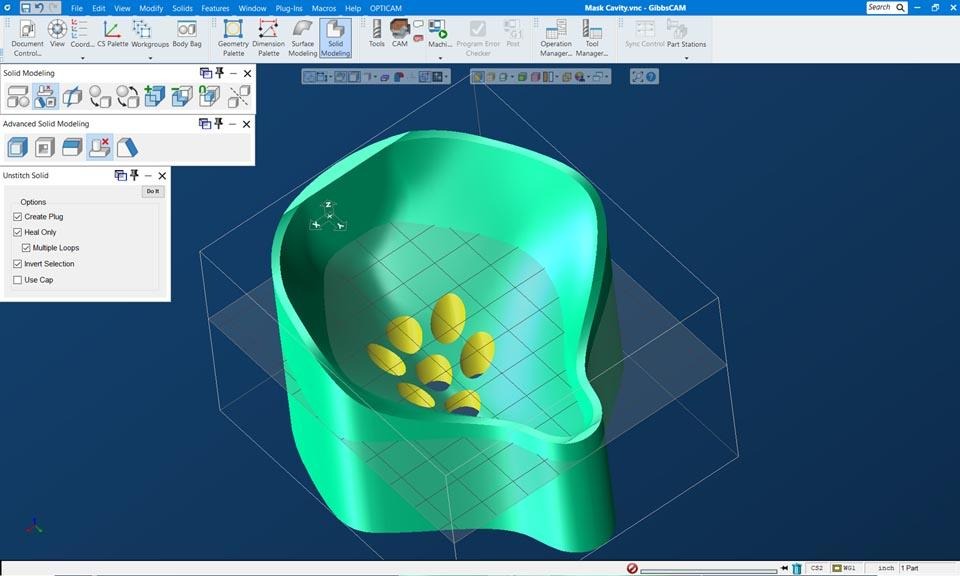
Figure 1 - Advanced Solid Modeling palette and Unstitch Solid dialog in GibbsCAM.
Step 3 - Remove One Connected Void with Edge Selection
Turn on Visible Edge Selection or Edge Selection so solid edges can be displayed and selected.
Select the external boundary edges where one connected hole or cavity breaks out into open space. For a through hole, selecting the top and bottom circular edges is a common example.
For an intersecting cavity, include every breakout edge that belongs to the same void, including smaller openings created by intersecting holes.
Leave Create Plug off unless a separate negative body of the filled void is required.
Select Do It and inspect the healed result.
Expected Result
The selected void is removed and the surrounding faces are extended or merged to close the model.
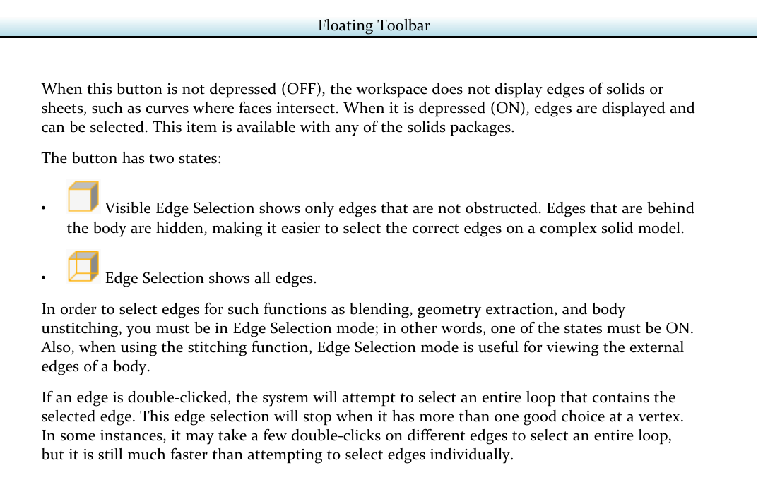
Figure 2 - Edge Selection states and the requirement for body unstitching.
Step 4 - Remove Multiple Features with Face Selection
Turn on Face Selection.
Select every face that belongs to each hole or void to be removed. Include cylindrical walls, conical faces, counterbore floors, and any other participating faces.
Select additional complete face sets when several separate voids should be removed in the same action.
Select Do It and inspect every affected location.
Expected Result
All completely selected feature face sets are removed in one action, provided GibbsCAM can heal the surrounding body.
Step 5 - Use Create Plug and Remove Other Feature Types
Enable Create Plug when a separate solid representing the negative volume of the selected void is useful.
Run Unstitch Solid. GibbsCAM removes the void from the working body and creates the plug as a separate body.
Use the plug for core-and-cavity work, inspection, or understanding a complex internal passage; otherwise, leave Create Plug off or delete the temporary plug after review.
To remove a fillet, chamfer, boss, counterbore, or spotface, select its complete face set and run Unstitch Solid.
Verify that the faces on both sides of the removed feature can merge into a valid healed surface.
Expected Result
The selected feature is removed, and an optional plug body exists only when Create Plug was enabled.
Step 6 - Select Many Holes with Automatic Feature Recognition
Open Features and use Hole Manager to run Automatic Feature Recognition for the round voids in the part.
Use Auto Group to organize the recognized holes when grouping makes selection easier.
Select one recognized group at a time, or select the full range of groups when all recognized voids should be removed.
Run Unstitch Solid with Create Plug off unless plug bodies are specifically required.
Inspect the defeatured model for unrecognized holes, incomplete face sets, or unintended removed geometry.
Expected Result
A large set of recognized holes is removed without manually selecting every individual face.
Step 7 - Validate and Use the Defeatured Body
Rotate, section, and inspect the simplified body from several views.
Confirm that the solid remains closed and that the healed faces are smooth and continuous where required.
Compare the simplified body with the preserved original and verify that only the intended features were removed.
Assign the body role required by the workflow, such as Stock, Part, or a process-model reference, and keep the original body available for final verification.
Regenerate affected operations and rerun the applicable simulation before releasing the program.
Expected Result
The simplified solid is valid for its intended stock, in-process, simulation, or toolpath-control role, while the original design body remains unchanged.
Selection Method Guide
Use the lightest selection method that reliably identifies the feature set. Complex intersections may require a different method than simple, isolated holes.
Best Practices
Keep the design model unchanged and make defeaturing changes only to a duplicate.
Use descriptive body names that identify the setup and intended role of each simplified body.
Use Visible Edge Selection first on crowded models; switch to full Edge Selection when hidden breakout edges must be selected.
For face-based removal, select the entire feature face set rather than only the most obvious cylindrical wall.
Use Create Plug only when the negative volume is needed; unnecessary plug bodies can clutter the Body Bag and cause selection mistakes.
Remove features in logical groups and inspect the model after each action instead of making one large, difficult-to-diagnose change.
Recreate a simplified body when the source design changes; do not assume an older defeatured copy still matches the current model.
Use the preserved design body for final dimensional and feature verification even when a simplified process model drives toolpath creation.
Video Tutorial

Troubleshooting
Problem: The edge selection states are not available or the edges cannot be selected.
Possible Causes
The installed license does not include the required solids option.
Face Selection is active instead of Visible Edge Selection or Edge Selection.
The body is hidden, not active, or not a valid solid or sheet body.
Resolution
Confirm the required solids option is licensed, show the working body, and turn on one of the two Edge Selection states before selecting breakout edges for Unstitch Solid.
Problem: Unstitch Solid reports that the edges split the body into more than two face sets.
Possible Causes
Breakout edges from more than one separate void were selected in the same edge-based action.
The selected edges do not describe one connected void boundary.
Resolution
Use Edge Selection for one connected void at a time. Clear the selection and select only the breakout edges belonging to one void, or switch to Face Selection and select complete face sets for multiple features.
Problem: The feature does not unstitch or the model cannot heal.
Possible Causes
One or more faces or breakout edges belonging to the feature were not selected.
The neighboring faces cannot be extended or merged into a valid replacement surface.
The feature intersects another void or external boundary that was not included in the selection.
Resolution
Inspect the feature from multiple views, include every participating face or breakout edge, and try the alternate selection method. If the surrounding surfaces cannot form a valid healed body, repair or remodel the region before continuing.
Problem: Unwanted geometry is removed with the selected feature.
Possible Causes
The selected faces belong to a larger connected region than expected.
Automatic Feature Recognition selected additional groups.
Invert Selection or another Unstitch Solid option is enabled unintentionally.
Resolution
Undo the action, compare the selection with the preserved original, clear unintended options, and remove the features in smaller logical groups. Review recognized feature groups before running Unstitch Solid.
Problem: Create Plug produces an unexpected or unnecessary body.
Possible Causes
Create Plug was left enabled from a previous operation.
The selected boundaries describe a larger or different void than intended.
Resolution
Undo the action, disable Create Plug when the negative volume is not required, and verify the complete boundary of the intended void. Delete temporary plug bodies after inspection if they are no longer needed.
Problem: Automatic Feature Recognition does not select every hole that should be removed.
Possible Causes
Some holes are not round, are interrupted, or do not meet the recognition settings.
Intersecting features were grouped differently from the expected selection.
Resolution
Review the recognized feature groups, adjust recognition settings when appropriate, and use Face Selection or Edge Selection for any remaining or complex voids. Always inspect the completed body for missed features.
Additional Information
Create Plug creates a separate solid that represents the negative of the removed void. It is useful in core-and-cavity work and for visualizing internal passages, but it is not required for routine hole, fillet, or chamfer removal.
Unstitch Solid is useful beyond stock preparation. A simplified process model can remove small holes or interruptions from a machining surface so an operation can generate the intended continuous toolpath. Confirm that the final operation still respects the original design requirements.
Interface artwork and option names can vary by GibbsCAM version. The Edge Selection reference is from the official GibbsCAM 2026 Common Reference, and the Unstitch Solid workspace image is from the official GibbsCAM GO Solid Milling page.
Related Articles
- Extracting Geometry from Solids
- Utilizing STL Models in GibbsCAM
- How to Import CAD Files and CAD Compatibilities
- Solid Model Looks Distorted
Explore More from CAMCO
Visit the CAMCO website to learn more about:
Keywords
GibbsCAM, Unstitch Solid, Defeature, Defeaturing, Solid Model, Advanced Solid Modeling, Edge Selection, Visible Edge Selection, Face Selection, Create Plug, Automatic Feature Recognition, AFR, Hole Manager, Heal Solid, Casting Stock, Forging Stock, In-Process Part, Process Model, Custom Stock Body