
Summary
This article explains how to convert completed 2D part geometry into a machinable solid model in GibbsCAM. The workflow extrudes closed profiles at their required Z ranges, unites additive bodies, subtracts temporary solids for steps and holes, and applies edge chamfers to finish the model.
The CAMCO tutorial uses a flange example with several stacked levels, a recessed step, three holes, and multiple chamfer sizes. Its dimensions illustrate the method; use the print, active coordinate system, and verified geometry for the production part.
Table of Contents
- Before You Begin
- Procedure
- Solid Modeling Operation Guide
- Best Practices
- Video Tutorial
- Troubleshooting
- Related Articles
Before You Begin
Complete and inspect the 2D geometry before starting the solid. Each extrusion profile must form the intended closed boundary without gaps, overlaps, or duplicate entities.
Confirm the part units, active coordinate system, origin, and the Z location of every flange level, pocket floor, step, and through feature.
Organize the geometry in a dedicated workgroup and keep a clean copy available in case profiles must be restored or corrected.
Display the Solid Modeling, Create Solids, and Advanced Solid Modeling palettes required by the installed GibbsCAM configuration.
Verify that the license includes the solid-modeling capabilities needed for Extrude, Union, Subtraction, and Blending.
Save a backup copy of the part before creating or combining bodies.
Important: The numerical Z ranges and chamfer sizes in the video belong to its sample part. Read all values from the current drawing or model and verify the finished body before generating toolpath.
Procedure
Step 1 - Review and Select the Source Geometry
Show the workgroup that contains the completed 2D part geometry.
Verify that the outside profile and each internal feature can be selected as a complete closed chain.
Determine which profiles add material and which profiles will create temporary cutting bodies for subtraction.
Record the start and end Z values for every extrusion from the print.
Expected Result
The geometry is clean, organized, and ready to drive each required solid feature.
Step 2 - Extrude the Base Level
Double-click the outside profile to select the complete chain.
Open Create Solids > Extrude.
Enter the start and end Z values for the lowest level. In the tutorial example, the profile is extruded from Z-1.000 to Z-1.250.
Select Do It and inspect the new solid body.
Expected Result
A solid body represents the lowest step of the part at the required depth and thickness.
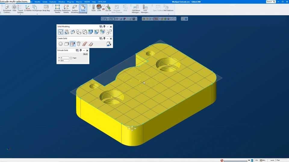
Figure 1 - GibbsCAM Extrude Solid applied to selected 2D profiles.
Step 3 - Build and Unite the Main Flange Levels
Select the profile for the next additive level and open Extrude again.
Enter its start and end Z values. The tutorial's intermediate level starts at Z0 and ends at Z-1.000.
When a required depth already exists in the geometry or another body, hold Alt to activate the interrogator cursor and click the source value instead of retyping it.
Select Do It to create the second body and confirm that it is correctly positioned relative to the base.
Select the additive bodies and apply Solid Modeling > Union so they become one solid piece.
Expected Result
The base and intermediate flange levels form one continuous solid body.
Step 4 - Create the Recessed Step with Subtraction
Select the geometry that bounds the recessed step. In the tutorial, two arcs are selected with Ctrl-click and their directions are reversed so the desired closed region is used.
Extrude the selected region through the depth of the recess. The tutorial example uses Z0 to Z-0.250.
If the new body is hidden by the main body, double-click or temporarily change body visibility to confirm that it was created.
Select the main part body first, then select the temporary step body that will remove material.
Apply Solid Modeling > Subtraction.
Expected Result
The temporary body is removed from the main solid, leaving the required recessed step and separate bosses.
Step 5 - Cut the Holes with Extruded Cylinders
Select the three hole circles or the hole profiles required by the print.
Extrude the profiles far enough beyond both sides of the part to create through-cutting cylinders. The tutorial uses Z1.000 to Z-2.000.
Extending the cutters beyond the body leaves exposed ends that are easy to select; it does not change the final part after subtraction.
Select the main part body first, then select all cylinder bodies.
Apply Subtraction and inspect every hole from more than one view.
Expected Result
The required holes pass completely through the solid and no temporary cutter bodies remain.
Step 6 - Hide Geometry and Apply Chamfers
Turn off Show Geometry so the solid edges are easier to see and select.
Enable Visible Edge Selection or Edge Selection, then select the edges that receive the same chamfer size.
Open Advanced Solid Modeling > Blending and choose Chamfer.
Enter the chamfer length from the print and select Do It. The tutorial applies 0.050, 0.020, and 0.025 chamfers to separate edge groups.
Repeat the selection and blending steps for each remaining chamfer size.
Expected Result
All specified edges have the correct chamfer, and the body remains a valid solid.
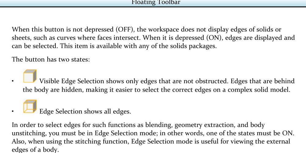
Figure 2 - Edge Selection must be enabled for blending operations such as chamfering.
Step 7 - Validate the Finished Solid
Rotate the model and inspect every flange level, boss, recess, hole, and chamfer.
Use the interrogator cursor or solid inquiry tools to compare critical dimensions with the print.
Confirm that the Body Bag contains the intended final body and no temporary extrusion or cutter bodies that could cause selection errors.
Show and hide the original geometry to compare it with the solid silhouette and feature locations.
Save the part, then use the solid as the part body for the appropriate milling operations and verify the generated toolpath in simulation.
Expected Result
One verified solid model matches the 2D design and is ready for solids-based programming and simulation.
Solid Modeling Operation Guide
Use the operation that matches whether the selected profile adds material, removes material, or finishes an existing edge.
Best Practices
Build the solid in a logical order: large additive levels first, then recessed features, holes, and edge finishing.
Use the drawing's actual Z datums. Do not copy the tutorial's values into another part.
When possible, extrude cutting bodies beyond the complete target body so through features are easy to select and verify.
For Subtraction, select the body to keep first and the body or bodies to remove second.
Use Visible Edge Selection when hidden edges create selection ambiguity; use full Edge Selection only when the required edge is obstructed.
Apply equal chamfers as a group, then change the value for the next edge group.
Save milestone copies after the additive body, after major subtractions, and after final blending when the model is complex.
Video Tutorial
Troubleshooting
Problem: Extrude does not create a solid.
Possible Causes
The selected geometry is open, disconnected, overlapping, or contains duplicate entities.
The selected chain does not define the intended closed region.
The required solid-modeling option is not available on the license.
Resolution
Inspect the chain endpoints, remove duplicates or overlaps, repair gaps, and select only the closed profile. If the command remains unavailable, verify the installed GibbsCAM options.
Problem: Union leaves separate bodies or fails.
Possible Causes
Not all additive bodies were selected.
The bodies do not touch or overlap, or one body is at an incorrect Z location.
A cutter body was selected instead of an additive body.
Resolution
Undo the union attempt, verify each body's extents and overlap, select only the bodies that add material, and apply Union again.
Problem: Subtraction removes the wrong body or produces the opposite result.
Possible Causes
The cutter body was selected before the main body.
The cutter does not fully intersect the intended material.
The wrong temporary extrusion was selected.
Resolution
Undo the result. Select the main body to keep first, then the cutter body or bodies, confirm their overlap, and apply Subtraction again.
Problem: A hole or recessed feature is incomplete.
Possible Causes
The cutting extrusion stops at or inside the target body instead of extending through it.
The profile was extruded from the wrong start or end Z value.
One or more cutter bodies were omitted from the subtraction selection.
Resolution
Recreate or extend the cutting body beyond the complete target volume, select every required cutter, repeat the subtraction, and inspect the result from both sides.
Problem: The intended chamfer edges cannot be selected.
Possible Causes
Edge Selection is off or the active state hides obstructed edges.
Geometry or another body overlaps the target edge.
The wrong selection mode is active.
Resolution
Hide unnecessary geometry or bodies, enable Visible Edge Selection or full Edge Selection as required, select the edges again, and apply Blending > Chamfer with the verified value.
Problem: The final solid does not match the 2D geometry or print.
Possible Causes
One extrusion used the wrong Z range or profile direction.
A required Union, Subtraction, hole, or chamfer was skipped.
The source geometry changed after the solid was created.
Resolution
Compare the body with the visible source geometry and interrogate critical dimensions. Restore the last valid milestone or rebuild the affected feature with the correct profile, Z values, and operation order.
Additional Information
The Alt-key interrogator cursor can capture dimensional data directly from solid models and 2D geometry, reducing re-entry errors when a required Z value already exists in the part. Always confirm that the selected source represents the intended datum.
The official GibbsCAM Common Reference states that Edge Selection must be enabled for blending and that Visible Edge Selection hides obstructed edges while full Edge Selection shows all edges. Double-clicking an edge can attempt to select its complete loop.
A solid model provides a clearer part representation and supports solids-based machining and verification, but it does not replace review of the drawing, toolpath, fixtures, posted program, and shop prove-out process.
Related Articles
- Extracting Geometry from Solids
- How to Import CAD Files and CAD Compatibilities
- Utilizing STL Models in GibbsCAM
- Solid Model Looks Distorted
Explore More from CAMCO
Visit the CAMCO website to learn more about:
Keywords
GibbsCAM, Creating Solid Model from 2D Geometry, 2D Geometry, Solid Model, Extrude Solid, Solid Modeling, Union, Subtraction, Boolean, Interrogator Cursor, Show Geometry, Edge Selection, Blending, Chamfer, Through Holes, Body Bag