
Summary
This article explains how GibbsCAM estimates program cut time, which timing result to use, and why an estimate can differ from the machine's actual cycle time. Accuracy depends mainly on the timing data in the Machine Definition Document (MDD), the programmed feeds and spindle speeds, machine-cycle behavior, and any feed or speed changes applied by the post processor.
Table of Contents
Before You Begin
Identify the result you need: a total program estimate or a sum of individual operation times.
Confirm that the active MDD represents the physical machine and that all operations to be measured are active.
Use a representative posted program and a measured machine cycle when validating the estimate.
Coordinate MDD or post-processor changes with the person responsible for machine definitions and posts.
Important: Calculated time is an estimate for planning and comparison. It does not replace posted-code review, machine prove-out, or shop safety procedures.
Procedure
Step 1 - Choose the Correct Timing Result
Use Reporter or Machine Simulation when you need the total program cut-time estimate.
Use Operation Manager when you need a sum of operation times. It includes rapid motion inside operations but does not include rapid motion between operations.
Compare the same active operations, operation sequence, part instances, and machine configuration each time.
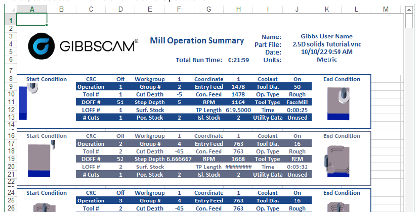
Figure 1 - Example Operation Report with Total Run Time and per-operation Time values.
Step 2 - Validate Timing Data in the MDD
Confirm that the active MDD is the definition used for the physical machine being estimated.
Verify the rapid speeds defined for the machine axes and flows. Incorrect rapid values affect non-cutting travel time throughout the program.
Verify tool-change time and any other MDD timing values used during inter-operation events, transfers, or machine transitions.
Base MDD timing values on documented machine data or repeatable measurements from the actual machine.
Save and test an approved copy of the MDD after any change. Do not alter timing data only to hide a difference caused by an unmodeled behavior.
Step 3 - Validate Operation Feeds and Conversions
Review the feedrate entered in each operation. GibbsCAM calculates feed time from the programmed operation feedrate.
For milling, confirm the programmed IPM or mm/min values. For turning, confirm the programmed IPR or mm/rev values.
When feed units are converted, verify the spindle speed and every input used in the conversion. An incorrect spindle speed produces an incorrect feed-per-revolution result.
Compare the posted feed and spindle commands with the operation data. Internal time reporting does not know about maximum feed, maximum speed, or other limits applied only by the post processor.
Step 4 - Account for Known Modeling Limits
Allow for acceleration and deceleration. GibbsCAM does not include the time required for the machine to reach or leave commanded feed and rapid speeds.
Allow for dog-leg rapid behavior. GibbsCAM assumes interpolated rapid motion, while some controls rapid each axis independently at its available rate.
Allow for machine cycles such as drilling or turning roughing. The exact motion and cycle execution time can differ from the path that GibbsCAM can estimate.
Expect acceleration effects to be more noticeable on programs with many short moves or on machines that take longer to reach commanded speed.
Step 5 - Measure and Calibrate
Generate the total estimate in Reporter or Machine Simulation and record the result.
Run the same posted program under comparable conditions and record the actual machine cycle time. Include only the events represented in the GibbsCAM estimate.
Compare the estimate with the actual cycle and identify whether the difference comes from MDD timing data, feed or spindle data, posted limits, machine cycles, or unmodeled motion behavior.
Correct traceable MDD or operation-data errors, regenerate the estimate, and repeat the comparison with more than one representative program.
Document any consistent remaining difference by machine and program type, and use the same timing source and measurement method for quoting and scheduling.
Expected Result
Reporter or Machine Simulation produces a repeatable total program estimate based on the active MDD and operation data. Operation Manager is understood as an operation-time subtotal. Any remaining difference from the physical machine is measurable and can be explained by known machine behavior, cycles, or post-applied limits.
Troubleshooting
Problem: Reporter or Machine Simulation differs significantly from the actual machine cycle.
Possible Causes
Rapid speeds, tool-change time, or other timing values are inaccurate in the MDD.
The machine spends significant time accelerating and decelerating, or it uses dog-leg rapids.
The posted program applies feed or speed limits that internal time reporting cannot see.
A drilling, turning roughing, or other machine cycle executes differently on the control.
Resolution
Validate the MDD values, operation feeds and spindle speeds, posted commands, and machine-cycle behavior. Correct traceable data errors, then compare the estimate and actual cycle again under the same conditions.
Problem: Operation Manager shows less time than Reporter or Machine Simulation.
Possible Causes
Operation Manager sums operation times and includes rapid motion within operations, but it does not include rapid motion between operations.
Different operations are active or selected in the compared results.
Resolution
Use Reporter or Machine Simulation for the total program estimate. Use Operation Manager only for operation-level comparison, and confirm that the same operations are active.
Problem: The estimated feed time is incorrect after feed-unit conversion or posting.
Possible Causes
The spindle speed used for a feed-per-minute or feed-per-revolution conversion is incorrect.
The post processor converts the feed or applies a maximum feed or speed limit.
The operation feedrate does not match the intended cutting condition.
Resolution
Verify the operation feedrate and spindle speed, then inspect the posted feed and speed commands. Adjust the source data or approved post configuration responsible for the difference; the internal estimator cannot account for limits added only during posting.
Problem: Programs with many short moves have a larger timing difference than expected.
Possible Causes
Acceleration, deceleration, control blending, and short-move filtering are not modeled in the calculated time.
Resolution
Confirm that feeds and MDD values are correct, then measure representative programs and document the repeatable machine-specific difference for planning.
Related Articles
- Using the Reporter
- Operation Manager Guide
- How to Use the Operation Summary
- Recommended Simulation Settings
Explore More from CAMCO
Visit the CAMCO website to learn more about:
Keywords
Accurate Cut Time, Program Time, Cycle Time, Total Run Time, Operation Time, MDD, Rapid Speed, Tool Change Time, Reporter, Machine Simulation, Operation Manager