
Summary
This article explains how to designate a GibbsCAM workgroup as Wrapped, display its geometry radially around a rotary axis, return the display to a flat view, and verify the related milling operation. The Wrapped workgroup setting and Wrap WGs command control geometry display and radial input mode; the operation's Rotate setting controls whether the toolpath uses simple positioning or Polar & Cylindrical Milling.
Before You Begin
Select a rotary machine configuration that supports the intended A-, B-, or C-axis workflow. A rotary machine must be active to create and view wrapped geometry.
Confirm that the Polar & Cylindrical Milling option is licensed and supported when continuous rotary interpolation is required.
Place the geometry in its own workgroup when practical, make that workgroup current, and confirm that the geometry is associated with the correct coordinate system.
Verify the geometry's depth or radius. Geometry at Depth 0 does not wrap around a nonzero radius.
Save a backup copy of the part before changing the workgroup designation, geometry depth, coordinate system, or process settings.
Important: Wrap and Unwrap change how designated workgroup geometry is displayed and how coordinate-entry dialogs behave. They do not automatically select a Polar & Cylindrical Milling strategy, validate rotary clearances, or prove that the post processor will output the intended motion.
Procedure
Step 1 - Prepare the Rotary Part and Workgroup
Open the part and select the intended rotary machine in the Document Control Dialog (DCD).
Open the Workgroup list and make the workgroup containing the radial geometry current.
Confirm that the geometry uses the correct coordinate system and is located at the intended nonzero depth or radius from the rotary axis.
Hide unrelated workgroups when necessary so the wrapped result can be inspected clearly.
Step 2 - Designate the Workgroup as Wrapped
Open Workgroup Info by double-clicking the workgroup name, or right-click the title bar of the Workgroup list and select WG Info.
Select Part Geometry in the Workgroup Info dialog.
Select the Wrapped checkbox, then close or apply the dialog.
Repeat the designation only for other workgroups that should participate in the wrapped display.
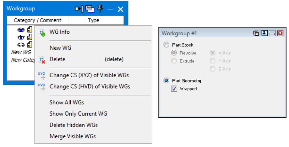
Figure 1 - Open WG Info and select Wrapped for a Part Geometry workgroup.
Step 3 - Wrap the Workgroup Display
Select Wrap WGs on the floating toolbar. As an alternative, choose Modify > Wrap > Wrap Geometry.
Confirm that geometry in the current Wrapped workgroup is displayed radially around the part at a radius equal to its defined depth.
Open a coordinate-entry dialog and confirm that GibbsCAM is in radial mode. Depending on the rotary axis, the dialog uses an angle and radius or diameter value instead of ordinary XYZ-only input.
Rotate the view and inspect the geometry around the circumference. Check the radius, angular location, seam area, orientation, and active coordinate system.
Step 4 - Unwrap the Workgroup Display
Turn off Wrap WGs or choose Modify > Wrap > Unwrap Geometry.
Confirm that the geometry returns to a flat display and that coordinate-entry dialogs return to the normal nonradial mode.
Leave the Wrapped checkbox selected when the workgroup is still intended for radial geometry and you only need a temporary flat view.
Select Wrap WGs again whenever the radial display is needed.
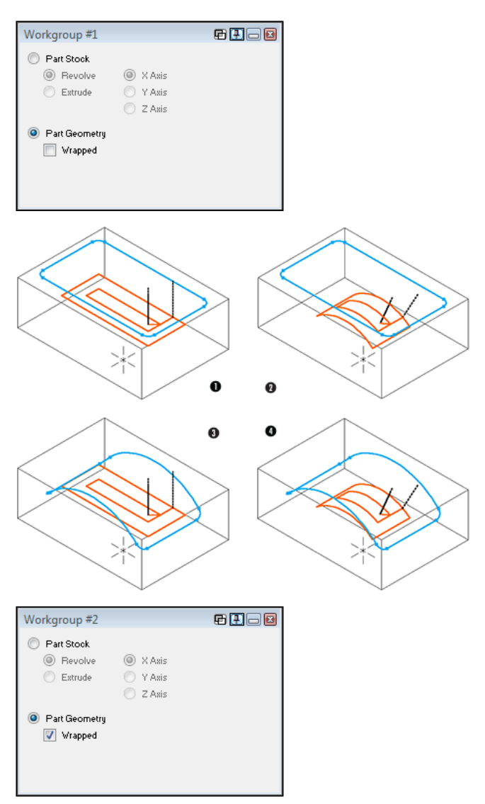
Figure 2 - Flat and wrapped workgroup displays with Position and Polar & Cylindrical toolpaths.
Step 5 - Verify the Machining Strategy
Open the milling process and review the Rotate settings for the operation.
Use Position only for simple indexed rotary positioning. Select Polar & Cylindrical Milling when the operation requires continuous rotary interpolation.
Regenerate the operation and inspect the toolpath in both flat and wrapped display modes. The display mode should not change the calculated Polar & Cylindrical toolpath.
Run Machine Simulation with the tool, holder, stock, fixtures, and machine components included in collision checking.
Post with the approved machine post, verify the rotary-axis output and direction, and complete the shop's normal prove-out procedure.
Wrap Controls and Their Purpose
Key distinction: The workgroup controls establish radial geometry and its display. The process Rotate setting establishes how the operation uses the rotary axis. Review both before regenerating toolpath.
Expected Result
The designated workgroup can be toggled between flat and radial display modes without losing its Wrapped designation. In radial mode, the geometry appears around the intended rotary axis at the correct radius and coordinate-entry dialogs use radial values. The regenerated operation follows the selected Position or Polar & Cylindrical Milling strategy and produces verified rotary-axis output.
Additional Information
Flat geometry is defined with XYZ values. Radial geometry uses an angular value and a radius or diameter; the labels depend on whether the machine rotates about the A-, B-, or C-axis.
When Wrap WGs is active, geometry in a current Wrapped workgroup at a depth other than Depth 0 is displayed around a radius equal to the geometry's depth.
Geometry does not need to be displayed as wrapped to be machined with Polar & Cylindrical Milling. The calculated toolpath is the same whether the selected geometry is viewed flat or wrapped.
Unwrap Geometry returns the display to flat mode and takes geometry dialogs out of radial mode. Use this command instead of clearing the Wrapped designation when only the view needs to change.
A wrapped display is not a collision check. Validate the complete toolpath, machine motion, workholding, post output, and physical setup before machining.
Source documentation: GibbsCAM 2026 Mill Reference, Polar & Cylindrical Milling, pages 184-188; and GibbsCAM 2026 Common Reference, Wrap/Stock and Wrap Workgroups, pages 87 and 123.
Troubleshooting
Problem: The Wrapped checkbox or Wrap WGs command is unavailable.
Possible Causes
The active DCD machine does not contain the required rotary-axis configuration.
Part Stock, rather than Part Geometry, is selected in Workgroup Info.
The wrong workgroup is current, or the local GibbsCAM configuration does not include the required rotary functionality.
Resolution
Select the intended rotary machine, make the correct geometry workgroup current, reopen WG Info, and select Part Geometry. If Wrapped or Wrap WGs remains unavailable, confirm the installed options and machine configuration with CAMCO Technical Support.
Problem: Wrap WGs is on, but the geometry remains flat or does not appear around the part.
Possible Causes
The current workgroup is not designated as Wrapped.
The geometry is located at Depth 0, so it has no nonzero radius around which to wrap.
The geometry is in a different, hidden, or noncurrent workgroup.
Resolution
Open WG Info for the geometry workgroup and select Wrapped. Confirm the geometry has the intended nonzero depth or radius, make the workgroup current and visible, then toggle Wrap WGs off and on again.
Problem: The geometry wraps at the wrong radius, angle, or direction.
Possible Causes
The geometry depth or radial value is incorrect.
The wrong coordinate system or rotary-axis orientation is active.
Radius-versus-diameter interpretation or the angular location does not match the machine setup.
Resolution
Unwrap the view, activate the correct coordinate system, and verify the geometry's depth, angular value, and radius or diameter convention. Correct the source geometry, wrap the view again, and inspect the seam and rotary direction before regenerating the operation.
Problem: The workgroup appears wrapped, but the toolpath does not use continuous rotary motion.
Possible Causes
The process Rotate setting is Position rather than Polar & Cylindrical Milling.
The operation was not regenerated after the process or geometry changed.
The selected machine, GibbsCAM option, or post processor does not support the intended continuous rotary output.
Resolution
Open the process Rotate settings and select Polar & Cylindrical Milling when continuous rotary interpolation is required. Regenerate, simulate, and inspect the posted rotary-axis output. If the option or correct output is unavailable, stop and have CAMCO review the license, machine definition, and post processor.
Related Articles
Explore More from CAMCO
Visit the CAMCO website to learn more about:
Keywords
GibbsCAM, Wrap Workgroup, Unwrap Workgroup, Wrap WGs, Wrapped Geometry, Radial Geometry, Flat Geometry, WG Info, Workgroup Info, Polar and Cylindrical Milling, Rotary Axis, A-axis, B-axis, C-axis, Rotary Interpolation