
Summary
This article explains how to configure a standard GibbsCAM milling Pocketing or Roughing process so an open pocket generally begins at the material boundary and works from the outside inward. The key setting is Offset from Part, Trim to Material on the Offset/Trim tab. Correct Air/Wall geometry, stock, and open-side settings are also required for the intended result.
Before You Begin
Create or identify the milling Pocketing or Roughing process and tool that will machine the open pocket.
Confirm the selected geometry, solid faces, stock definition, cut depth, step-over, feeds, and spindle speed are correct for the operation.
For wireframe open pockets, designate edges that the tool may cross as Air geometry. Leave protected part edges as Wall geometry.
Save a backup copy of the part before changing pocket boundaries, stock behavior, or process settings.
Important: Offset from Part, Trim to Material generally produces outside-in motion for open pockets; the actual result depends on the part, material boundary, Air/Wall designations, stock, and other process settings. Always regenerate, simulate, inspect the posted program, and follow the shop's prove-out procedure.
Procedure
Step 1 - Prepare the Pocket Operation
Open the part and select the geometry, solid face, or machining feature that defines the pocket.
Create the intended milling Pocketing or Roughing process, or open the existing process for editing.
Choose an Offset-based roughing style and enter the required Surface Z, Floor Z, depth increments, step-over, feeds, spindle speed, stock allowances, and entry settings.
If the pocket has an open side, verify that the open edge is represented by Air geometry or by the applicable solid-and-stock material boundary.
Step 2 - Select Offset from Part, Trim to Material
Open the Offset/Trim tab in the process dialog.
Select Offset from Part, Trim to Material.
When the traverse control is available, use Retract and Rapid for the initial verification unless a different linking move has already been reviewed and approved for the machine.
Apply or close the process dialog, then select Do It or Redo to regenerate the operation.
Figure 1 - Offset from Part, Trim to Material generally starts an open-pocket toolpath from the outside in.
Step 3 - Review Open-Side Controls
Open the Open Sides tab when one or more boundaries are open or defined as Air.
Set Clearance to control how far the inner edge of the tool approaches from the Air wall or open material edge.
Set Overhang to control how far the tool overlaps an Air edge while moving parallel to it. If no value is entered, GibbsCAM can use the tool's cutting radius.
Review Minimum Cut so the operation does not create unwanted passes for insignificant remaining material.
Regenerate the operation after changing any open-side value.
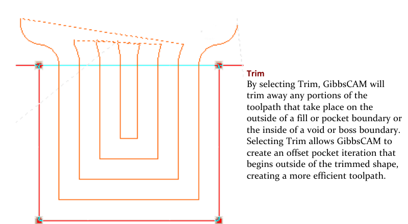
Figure 2 - Trim removes toolpath outside the material boundary and can begin the offset iteration outside the trimmed shape.
Step 4 - Verify the Toolpath and Output
Display the regenerated operation and confirm that the tool approaches from the intended open side and the cutting passes progress from the material boundary inward.
Check the entry, linking moves, retracts, step-over, full-diameter engagement, finish allowance, and clearance from fixtures and protected walls.
Run Op Simulation and, when applicable, Machine Simulation with stock, tool, holder, fixtures, and machine components included.
Post with the approved machine post, review the rapid and feed moves between trimmed segments, then follow the shop's dry-run and prove-out procedure.
Expected Result
The regenerated open-pocket operation approaches from the permitted Air or material boundary and generally removes material from the outside inward. The passes remain close to the programmed step-over, avoid unnecessary full-diameter engagement, respect Wall geometry and fixtures, and produce reviewed linking moves in the posted program.
Additional Information
Offset from Part, Trim to Material is the recommended general setting for many open pockets because it allows toolpath to be trimmed by the material boundary and permits rapid motion in air.
Offset from Part and Material is a different mode intended to keep the tool engaged. It does not provide the same trimmed outside-in behavior.
Fewest Offsets from Part, Offset from Material can be useful for core parts with a large volume of material around a complex boss.
The Advanced Offset/Trim mode provides separate Offset, Trim, or Fewest Offsets control for Pocket, Fill, Void, and Boss boundaries.
A trimmed path must be linked between segments. Retract and Rapid, Direct Rapid, and Direct Feed may be available. Review the complete path before using Direct Rapid because machine rapid motion is not always a straight line.
When Pocketing combination geometry that contains both Air and Wall elements, the GibbsCAM Mill reference does not recommend selecting Cutter Radius Compensation (CRC). When a finish pass is required, use the appropriate Trimmed finish pass setting so only Wall geometry is finished. For a complete Air loop, Overhang does not apply; use Cut Width instead.
Source documentation: GibbsCAM Mill Reference, Processes > Open Sides and Offset/Trim tabs, pages 129-133.
Troubleshooting
Problem: The operation still starts inside the pocket.
Possible Causes
Offset from Part, Trim to Material was not selected, or the process was not regenerated after the change.
The pocket is closed and provides no Air or material boundary from which the tool can enter.
An open edge is incorrectly designated as Wall geometry, or the stock boundary conflicts with the intended opening.
Resolution
Reopen the Offset/Trim tab, select Offset from Part, Trim to Material, and regenerate. Verify the open edge is represented by Air geometry or the correct solid-and-stock boundary. Then inspect the regenerated entry and first offset before simulation.
Problem: The toolpath retracts more often than expected between passes.
Possible Causes
Trimming created separate toolpath segments that require linking moves.
Retract and Rapid is selected for traverse between trimmed segments.
The part or material boundary divides the path into many disconnected regions.
Resolution
Review the selected boundaries and remove unintended breaks. If fewer retracts are required, evaluate the available traverse modes with Op Simulation and Machine Simulation before changing them. Do not use Direct Rapid until the complete move is proven safe for the machine.
Problem: The toolpath crosses a protected edge or does not extend through the intended open side.
Possible Causes
Air and Wall geometry are reversed or incomplete.
Use Stock is creating a material boundary that conflicts with the selected geometry.
Open Sides Clearance or Overhang is inappropriate for the tool and boundary.
Resolution
Correct the Air/Wall designations, verify the stock definition and Use Stock behavior, and review Open Sides Clearance and Overhang. Regenerate and inspect the path at every depth before posting.
Problem: The finish path follows an Air wall or Cutter Radius Compensation behaves unexpectedly.
Possible Causes
The process uses combination geometry containing both Air and Wall elements.
CRC is enabled for a Pocketing process where the trimmed finish behavior is more appropriate.
The Trimmed finish pass option is not selected in the applicable Offset/Trim mode.
Resolution
Review the combination geometry and keep only true part boundaries designated as Wall. Follow the GibbsCAM Mill guidance for the selected process: use the applicable Trimmed finish pass setting instead of CRC when required, then regenerate and verify the posted compensation output.
Related Articles
Explore More from CAMCO
Visit the CAMCO website to learn more about:
Keywords
GibbsCAM, Pocketing, Roughing, Outside In, Open Pocket, Offset from Part Trim to Material, Offset Trim, Air Geometry, Wall Geometry, Open Sides, Clearance, Overhang, Minimum Cut, Trimmed Toolpath, Mill