
Summary
This article explains how to calculate a linear milling feed rate, compensate it for internal and external circular paths, and verify how GibbsCAM, the post processor, and the CNC control interpret the programmed feed. Internal circular cuts normally require a lower tool-center feed, while external circular cuts normally require a higher tool-center feed to maintain the intended cutting-edge feed.
Table of Contents
Before You Begin
Obtain the cutting-tool manufacturer's recommended chip load or linear feed for the tool, workpiece material, and operation.
Record the effective cutter diameter, number of cutting edges, intended spindle speed, and the finished hole or boss diameter at the cutting surface.
Confirm the part units and feed mode that GibbsCAM will use and the post will output, such as inches per minute, millimeters per minute, feed per tooth, or feed per revolution.
Determine whether the CNC control or post processor automatically compensates circular feed at the cutting edge, including any behavior associated with cutter radius compensation.
Use an approved post processor and retain a backup copy of the part before changing a production operation.
Important: Do not apply a manual circular-feed correction when the post or CNC control already applies the same correction. Double compensation can create an unsafe feed rate.
Procedure
Step 1 - Determine the Feed Basis and Output Mode
Review the tool manufacturer's data and confirm that the recommendation applies to the selected milling tool, material, and type of cut.
Identify whether the recommendation is a chip load per tooth, a feed per revolution, or a linear feed in inches or millimeters per minute.
Identify the GibbsCAM feed field used by the operation and the feed mode or units that the post processor will output.
Verify whether the control interprets the programmed feed at the tool centerline or compensates it to maintain feed at the cutting edge. Consult the control and post documentation when uncertain.
Step 2 - Calculate the Linear Target Feed
Record the recommended chip load per tooth (fz), the number of cutting edges (z), and the achievable spindle speed (RPM).
Calculate the linear feed using Flinear = fz × z × RPM. The result is IPM when fz is IPT, or mm/min when fz is mm/tooth.
If the manufacturer already supplies a linear feed for the exact tool and condition, use that value as Flinear.
If the calculated spindle speed exceeds the machine limit, use the achievable RPM and recalculate Flinear to preserve the intended chip load.
Check the result by calculating fz = Flinear / (z × RPM) and comparing it with the recommendation.
Step 3 - Identify the Circular-Path Geometry
Classify the path as internal (inside a hole or pocket) or external (around a boss or outside profile).
For an internal path, use the finished hole diameter as D1. For an external path, use the finished boss or profile diameter as D1.
Use the effective cutter diameter at the cutting contact as D2. Do not automatically substitute the shank diameter for tapered, chamfer, or form tools.
Use the same units for D1 and D2. For an internal circle, D1 must be greater than D2.
Step 4 - Calculate the Circular Tool-Center Feed
If the control or post does not compensate circular feed, calculate the programmed tool-center feed with the applicable formula.
Internal (ID): Fcenter = Flinear × (D1 − D2) / D1
External (OD): Fcenter = Flinear × (D1 + D2) / D1
For an internal path, confirm that the result is lower than Flinear. For an external path, confirm that the result is higher than Flinear.
Round the result only as much as the GibbsCAM field, post format, or shop standard requires. Avoid early rounding during the calculation.
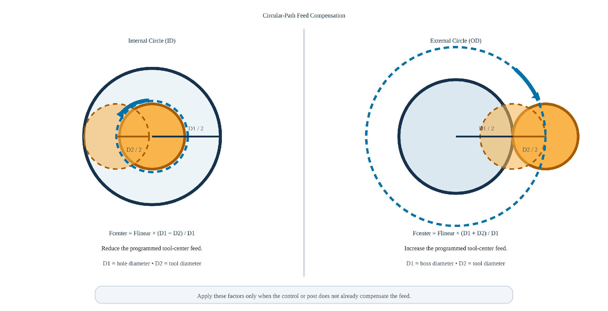
Figure 1 - Internal and external circular-path feed compensation.
Step 5 - Review a Worked Example
Use a linear feed of 8.3 IPM, a finished diameter D1 of 0.562 inch, and a cutter diameter D2 of 0.370 inch. These values mirror the thread-milling example in the Related Reference.
Calculate the internal factor: (0.562 − 0.370) / 0.562 = 0.3416. The internal tool-center feed is 8.3 × 0.3416 = 2.84 IPM, commonly rounded to 2.8 IPM.
Calculate the external factor: (0.562 + 0.370) / 0.562 = 1.6584. The external tool-center feed is 8.3 × 1.6584 = 13.76 IPM, commonly rounded to 13.8 IPM.
Step 6 - Enter and Verify the Feed in GibbsCAM
Enter the calculated tool-center feed in the applicable GibbsCAM operation only when manual compensation is required for the selected post and control.
Generate the operation and verify that the toolpath uses the intended internal or external radius and the correct cutter diameter.
Post the operation and inspect the feed command, feed mode, units, cutter compensation state, and any post-applied feed limits or conversions.
Confirm that the control will not apply an additional non-linear or tool-edge feed correction to the value already calculated.
Run Op Simulation and, when applicable, Machine Simulation, then follow the shop's single-block, dry-run, and prove-out procedure while monitoring chips, spindle load, sound, and finish.
Expected Result
The programmed feed maintains the intended cutting-edge feed for the selected linear, internal circular, or external circular path. The posted NC program uses the expected feed mode and value without duplicate compensation, and the operation is verified before production use.
Related Reference
Harvey Performance - Speeds and Feeds 101 (see the Non-Linear Path section)
Additional Information
The circular factors preserve the intended tangential cutting-edge feed for a planar circular path. Helical interpolation also contains an axial component, so confirm the tool manufacturer's and control builder's guidance for demanding thread-milling or helical applications.
The correction becomes larger as the cutter diameter approaches the internal hole diameter. An extremely small internal factor may indicate that the selected tool is too large for the path or that the diameters were entered incorrectly.
For partial arcs or varying radii, use the diameter associated with the active arc. A single correction may not represent a toolpath whose centerline radius changes continuously.
Some controls can maintain feed at the cutting edge when cutter radius compensation or a control-specific edge-feed function is active. This behavior is controller- and post-dependent.
When the post converts between feed per tooth, feed per minute, or feed per revolution, the accuracy of the output also depends on the correct spindle speed, tooth count, units, and post limits.
Manufacturer cutting data is a starting point. Reduce or refine the proven feed when required by tool engagement, rigidity, runout, workholding, machine limits, material condition, or finish requirements.
Troubleshooting
Problem: An internal circular cut overloads the tool or produces poor finish even though the manufacturer's linear feed was used.
Possible Causes
The linear feed was programmed directly without reducing it for the smaller internal tool-center path.
The hole diameter or effective cutter diameter used in the factor is incorrect.
The control or post feed behavior was assumed rather than verified.
Resolution
Confirm D1 and D2, determine whether the programmed value represents tool-center or cutting-edge feed, and apply the internal factor only once. Repost and prove out the revised operation.
Problem: An external circular cut runs too slowly, rubs, or produces a chip load below the recommendation.
Possible Causes
The linear feed was not increased for the larger external tool-center path.
An internal subtraction factor was used for an external profile.
A post limit or machine override reduced the commanded feed.
Resolution
Use the boss diameter for D1 and the effective cutter diameter for D2, calculate the external addition factor, and verify the posted feed and active overrides before proving out the change.
Problem: The posted feed does not match the value entered in GibbsCAM.
Possible Causes
The post converts the input between feed per tooth, feed per revolution, and feed per minute.
The post applies a maximum feed, spindle-speed dependency, unit conversion, or another custom rule.
A control-specific circular or cutter-compensation function changes how the programmed feed is interpreted.
Resolution
Confirm the GibbsCAM input units, spindle speed, tooth count, post settings, and active control modes. Review the complete posted block and have the approved post developer inspect any unexplained conversion.
Problem: The calculated internal feed is zero, negative, or unreasonably small.
Possible Causes
The cutter diameter is equal to or greater than the finished hole diameter.
Radius and diameter values were mixed, or the values use different units.
The programmed path diameter was substituted for the finished cutting diameter and the tool radius was subtracted twice.
Resolution
Stop and recheck the geometry. Use finished diameters for D1, the effective cutter diameter for D2, and consistent units. Select a smaller tool or revise the strategy when D1 is not greater than D2.
Related Articles
- Accurate Cut Time Calculation
- Recommended Simulation Settings
- Error: "Fatal Post Error"
- How to Create a Pack and Go File
Explore More from CAMCO
Visit the CAMCO website to learn more about:
Keywords
Feed Rate Calculation, Circular Interpolation, Non-Linear Path, Internal Feed, External Feed, Tool Center Feed, Cutting Edge Feed, Chip Load, Feed Per Tooth, IPM, Millimeters Per Minute, Cutter Radius Compensation, GibbsCAM