
Summary
This article explains the Cutter Radius Compensation (CRC) types available in GibbsCAM and how each type changes the posted coordinate path and the value entered in the CNC control's compensation register. Tool Center is the recommended general setting. Tool Edge and Finish Profile shift more of the offset calculation to the control and therefore require a compatible post, correct register values, and careful verification.
Before You Begin
Confirm which CRC method the approved post processor and CNC control are designed to use. Do not infer the required method from another machine or post.
Record the programmed tool radius, the measured radius of the actual tool, and any stock allowance that must remain on the finish profile.
Verify the Cutter Compensation Offset number assigned to the tool so the posted D number addresses the intended control register.
Save a backup copy of the part and retain the last proven NC program before changing the CRC type or control offset.
Important: Changing the CRC type does not change the orange toolpath or cut-part rendering shown in GibbsCAM; those displays remain tool-center representations. The posted coordinates and the control's offset behavior can still change substantially. Always inspect the NC output and prove out the program.
CRC Type Comparison
Key distinction: The CRC type determines what path GibbsCAM sends to the post and what compensation belongs in the control register. The operation's CRC On setting and its entry/exit moves determine where compensation is activated and canceled.
Procedure
Step 1 - Set the Default CRC Type
Select File > Preferences.
Select Machining Prefs.
Choose the approved method from Default Mill CRC: Tool Center, Tool Edge, Finish Profile, or Last Used.
Use Tool Center unless the machine, post, and shop procedure specifically require another type.
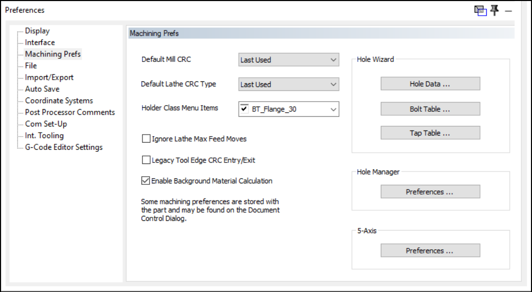
Figure 1 - Set the default Mill or Lathe CRC type in File > Preferences > Machining Prefs.
Step 2 - Confirm the Current Part's CRC Type
Open the Document Control Dialog (DCD) for the current part.
Open Machining Preferences.
Review the Mill CRC Type stored with the part and override the application default when the approved post or machine setup requires a different type.
Record the selected type in the setup documentation or operation notes when the shop requires traceability.
Step 3 - Configure the Operation and CRC Moves
Open the Contouring, Roughing, Bore, or supported finishing process that will use compensation.
Enable CRC On only when the post and control are intended to output and use cutter compensation for the operation.
Create suitable linear entry and exit moves. Many controls require CRC to activate on the entry line and cancel on the exit line, commonly through G41/G42 and G40 output.
Verify that the approach and exit lengths are long enough for the control to apply and remove the offset without an alarm or an unintended move.
Regenerate the operation after changing the process, CRC type, tool, stock, entry, or exit values.
Step 4 - Enter the Correct Control Offset
For Tool Center, enter the difference between the measured actual radius and the programmed radius. Use 0 when they match.
For Tool Edge, enter the full actual tool radius, adjusted as required for a tapered tool or corner radius.
For Finish Profile, enter the full tool radius plus the stock allowance that must remain.
Confirm that the value is entered in the register addressed by the posted D number and that the sign convention matches the control and shop standard.
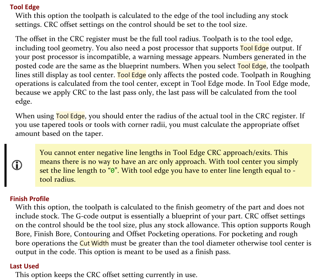
Figure 2 - Official GibbsCAM reference guidance for Tool Edge, Finish Profile, and Last Used.
Step 5 - Verify the Posted Program
Post the operation with the approved machine post and locate the compensation register address, CRC activation, first compensated cut, cancellation, and exit move.
Confirm that the coordinate path matches the selected CRC type and that the intended tool radius or wear value is not being applied twice.
Run Op Simulation and Machine Simulation, understanding that the displayed path remains tool-center based and does not prove the control's own offset calculation.
Follow the shop's single-block, dry-run, graphics, and prove-out procedure while monitoring the first compensated move and the finished size.
Expected Result
The part uses the intended CRC type, the post outputs the expected coordinate path and compensation commands, and the referenced control register contains the correct radius or wear value. Compensation activates and cancels on safe moves, the tool cuts on the correct side of the geometry, and the finished size can be adjusted according to the approved shop method.
Additional Information
Tool Center is recommended because GibbsCAM draws and renders every CRC type as a tool-center path. It also leaves the control register available for small wear or measured-size corrections.
With Tool Center, a smaller actual tool can use a negative difference value according to the GibbsCAM reference. Confirm the sign convention on the specific control before editing a production offset.
Tool Edge requires a post processor that supports Tool Edge output. An incompatible post can display a warning.
Finish Profile is intended as a finish-pass method. For offset pocketing and rough-bore applications, the Cut Width must be greater than the tool diameter or tool-center output may be used instead.
Changing the default in File > Preferences does not guarantee that an existing part changes; the DCD can store a part-specific CRC type.
Converted toolpath geometry reflects the selected CRC type even though the on-screen toolpath display itself remains tool-center based.
Do not use Tool Edge for turning custom form tools; the complete form is used in the calculation. Use the method approved for the tool, post, and control.
Related Video
Troubleshooting
Problem: The orange toolpath does not move after the CRC type is changed.
Possible Causes
GibbsCAM displays and renders all CRC types as a tool-center path.
The operation was not reposted after the preference changed.
The part-specific DCD setting is overriding the application default.
Resolution
Treat the unchanged display as expected. Confirm the current part's CRC type in the DCD, regenerate and repost the operation, then compare the NC coordinates and compensation commands rather than relying on the orange path alone.
Problem: The finished feature is oversized or undersized after CRC is applied.
Possible Causes
The control register contains a full radius when Tool Center expects only the radius difference, or it contains only wear when Tool Edge expects the full radius.
The tool diameter, stock allowance, or offset sign is incorrect.
Compensation was applied in both GibbsCAM and the control for the same amount.
Resolution
Stop the program and compare the selected CRC type, programmed tool radius, measured tool radius, stock allowance, posted D number, and register value. Correct only the value required by the approved method, repost if necessary, and re-prove the first compensated cut.
Problem: The post reports that Tool Edge output is unsupported or the NC path is unexpected.
Possible Causes
The selected post processor does not support Tool Edge output.
A part-specific CRC setting differs from the method used when the post was developed.
The operation type or roughing behavior does not support the expected edge-based output on every pass.
Resolution
Return to the approved CRC type, normally Tool Center, and repost. Do not suppress the warning or alter the register to compensate for an unapproved path. Contact CAMCO Post Support when the machine must use Tool Edge output.
Problem: The control alarms when G41 or G42 activates, or when G40 cancels.
Possible Causes
The entry or exit line is missing, too short, or incompatible with the control's compensation rules.
The full radius in the register is larger than the available activation move.
The post outputs compensation on a move or plane the control does not allow.
Resolution
Cancel the run and review the control alarm description. Lengthen or redesign the linear entry and exit moves, confirm the register value and active plane, then repost and verify the exact activation and cancellation blocks before another dry run.
Problem: Finish Profile outputs tool-center coordinates instead of the expected finish profile.
Possible Causes
The operation is not one of the supported Finish Profile applications.
For offset pocketing or rough bore, Cut Width is not greater than the tool diameter.
The current part is using a different CRC type than the application default.
Resolution
Verify the operation type and the DCD CRC setting. For supported pocketing or rough-bore use, set Cut Width greater than the tool diameter when appropriate, regenerate, and inspect the reposted coordinates. Use Tool Center if the operation cannot safely meet the Finish Profile requirements.
Related Articles
Explore More from CAMCO
Visit the CAMCO website to learn more about:
Keywords
GibbsCAM, CRC, Cutter Radius Compensation, Tool Center, Tool Edge, Finish Profile, Last Used, G40, G41, G42, Cutter Compensation Offset, D Offset, Wear Offset, Tool Radius, Stock Allowance, Machining Preferences, Mill