
Summary
This article explains how to import or draw a mill-tool profile, prepare the geometry for GibbsCAM, create a 2D Form tool, choose how the profile is used for toolpath generation, and apply the tool to a 2D milling operation. A valid profile is one connected, open shape in the XY plane, drawn around X0 with the tool tip at the original coordinate-system origin.
Before You Begin
Obtain an accurate 2D tool profile from the tool manufacturer, commonly as a DXF file, or draw the profile in GibbsCAM.
Confirm the manufacturer's programmed diameter, programming radius or Virtual Corner Radius, holder data, stickout, recommended feeds and speeds, and any non-cutting portions of the profile.
Use a Mill part and the original coordinate system while preparing the profile. Keep the imported profile in a separate workgroup when practical.
Save a backup copy of the part before translating, trimming, joining, or reclassifying the source geometry.
Important: A visually correct tool does not guarantee correct toolpath or posted motion. Verify the profile, contact model, operation depth, holder, simulation, and NC output before machining.
Profile Requirements
Procedure
Step 1 - Import or Draw the Tool Profile
Choose File > Import and select the manufacturer's 2D profile file, such as a DXF, or draw the profile in GibbsCAM.
If the imported geometry is gray, open the Workgroup list and select the workgroup created for the imported layer so its geometry becomes current.
Hide or delete dimensions, centerlines, labels, duplicate entities, and other geometry that is not part of the tool outline.
Confirm that the remaining profile represents one side of the rotational tool shape rather than a full closed cross-section.
Step 2 - Prepare the Geometry
Confirm that the profile lies in the XY plane of the original coordinate system.
Double-click an element to chain-select the complete profile. Repair gaps, overlaps, branches, or disconnected elements until one continuous open chain is selected.
Choose Modify > Absolute Translate. Capture the current coordinates of the tool tip, then translate that point to X0, Y0, Z0.
Verify that the profile is drawn around X0, which is the axis about which GibbsCAM revolves the selected geometry.
For any non-cutting profile section, right-click the geometry and change its designation from Wall to Air.
Step 3 - Create the 2D Form Tool
Keep the prepared profile selected.
Double-click an empty tool tile to open the tool-type selection.
Select 2D Form from the mill tool types.
In the Tool Creation dialog, select Apply to load the selected profile.
Confirm that the tool diagram matches the intended revolved shape and orientation.
Enter the tool number, description, flutes, material, holder, stickout, and other required tool data.
Enter Nominal Diameter only when the manufacturer-specified nominal value must differ from the diameter GibbsCAM calculates from the profile.
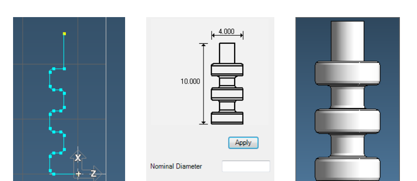
Figure 1 - Connected profile geometry, the loaded tool diagram, and the rendered 2D Form tool.
Step 4 - Choose the Toolpath Contact Model
Open Generate toolpath from in the Tool Creation dialog.
Use Real profile when the actual profile and any valid undercutting shape must be considered. This is the most accurate and most computation-intensive option.
Use Monotonic profile when narrowing portions of the tool must not create undercut contact; GibbsCAM preserves shank clearance by using the widest contact radius below the geometry depth.
Use Nominal parameters only when the manufacturer supplies a nominal diameter and Virtual Corner Radius or programming radius for bullnose-style programming.
If the profile contains splines, review Spline Machining Tolerance in DCD > Machining Preferences before generating the operation.

Figure 2 - Generate toolpath from options for a 2D Form tool.
Step 5 - Use and Verify the Tool
Drag the completed 2D Form tool to an empty Process tile or select it in the intended 2D milling process.
Create or edit the supported 2D operation, such as a Contour operation, and enter the correct Surface Z, Final Depth, stock, feeds, spindle speed, entry, exit, and clearance values.
Generate the operation and inspect the tool-center path, contact area, cutting side, depth, and clearance from the part and holder.
Run Op Simulation and, when machine motion or holder clearance matters, Machine Simulation with the correct tool, holder, stock, fixtures, and machine components.
Post with the approved machine post, review the output against the manufacturer's programming method, and follow the shop's dry-run and prove-out procedure.
Expected Result
The selected open profile loads into the Tool Creation dialog and produces the intended revolved 2D Form tool. The tool can be assigned to a supported 2D milling operation, the selected contact model generates the expected toolpath, and simulation displays the actual tool profile without unintended collisions. The posted program is reviewed and proven before production.
Additional Information
Real profile, Monotonic profile, and Nominal parameters change how GibbsCAM calculates contact points for toolpath generation. Material Only and rendering use the real profile whenever possible.
Nominal parameters treats the tool as a bullnose mill for toolpath calculation while retaining the actual form-tool shape for rendering. Use the manufacturer's supplied nominal diameter and programming radius.
For 2D milling, GibbsCAM offsets the form tool as though the selected geometry is at Surface Z and the tool is at Final Depth. This is similar to the offset behavior for tapered or bottom-corner-radius tools.
Mill 2D Form tools are not compatible with 3D milling. Use a supported 2D process or a suitable 3D Form tool workflow.
Complex profiles can increase calculation and cut-part rendering time. Use only the geometry required to define the tool.
The supplied video demonstrates importing a DXF, moving the tool tip to the original origin with Absolute Translate, creating the tool, and applying it to a Contour operation.
Source documentation: GibbsCAM 2026 Mill Reference, Tools > 2D Form Tool, pages 31-33; CAMCO GibbsCAM Tech Tip, How to Create and Use 2D Form Tools.
Related Video
Troubleshooting
Problem: The selected profile does not load after Apply is selected.
Possible Causes
The profile is closed, branched, disconnected, or contains a gap or overlapping entity.
The profile is not in the XY plane or is not drawn around X0.
Unrelated geometry was included in the chain selection.
Resolution
Return to the profile workgroup, isolate the intended outline, and repair it into one connected open chain in the XY plane. Confirm that the chain is drawn around X0, select it again, and apply it to a new 2D Form tool.
Problem: The tool is inverted, offset, or revolved into the wrong shape.
Possible Causes
The tool tip was not translated to X0, Y0, Z0 of the original coordinate system.
The profile was imported with the wrong orientation or scale.
The wrong side of the rotational profile or a full closed cross-section was selected.
Resolution
Verify file units and orientation, translate the intended tool tip to the original origin, and keep only the connected half-profile required for revolution about X0. Recreate the tool and compare the diagram with the manufacturer's drawing.
Problem: A non-cutting part of the tool removes material or changes the toolpath.
Possible Causes
The non-cutting profile element is still designated as Wall.
Real profile is considering geometry that should not participate in contact calculation.
Unnecessary holder or shank geometry was included in the selected chain.
Resolution
Remove geometry that belongs in the holder definition instead of the cutting profile. For non-cutting elements that must remain in the profile, change their designation from Wall to Air, recreate the tool, regenerate the operation, and verify the result.
Problem: The generated path differs from the manufacturer's programmed diameter or programming radius.
Possible Causes
Generate toolpath from is set to Real profile or Monotonic profile instead of Nominal parameters.
Nominal Diameter or Virtual Corner Radius does not match the manufacturer's programming data.
The post or operation applies an additional offset or compensation method.
Resolution
Review the manufacturer's programming instructions and select the matching contact model. For Nominal parameters, enter the approved Nominal Diameter and Virtual Corner Radius. Regenerate, inspect the posted coordinates and compensation, and prove out the operation before production.
Problem: Toolpath generation or simulation is slower than expected.
Possible Causes
The form-tool profile contains excessive segments or tightly fitted splines.
Real profile is being used even though an approved simplified contact model is suitable.
Rendering settings are too detailed for routine review.
Resolution
Remove unnecessary profile entities and verify Spline Machining Tolerance. Use Monotonic profile or Nominal parameters only when technically appropriate and supported by the manufacturer's data. Use balanced simulation settings for routine review, then restore the required accuracy for final verification.
Related Articles
- How to Import CAD Files and CAD Compatibilities
- Recommended Simulation Settings
- Understanding CRC Types
Explore More from CAMCO
Visit the CAMCO website to learn more about:
Keywords
GibbsCAM, 2D Form Tool, Form Tool, Custom Tool, Tool Profile, DXF, Tool Creation, XY Plane, X0, Absolute Translate, Real Profile, Monotonic Profile, Nominal Parameters, Nominal Diameter, Virtual Corner Radius, Spline Machining Tolerance, Contour