
Summary
This article explains how to create and use Watches in GibbsCAM Machine Simulation. A Watch compares a selected Datum with a Reference, continuously reports their relative location during rendering, and can display either a Distance line or the Path taken by a point. Watches are available only in Machine Simulation.
Before You Begin
Regenerate the operations that will be reviewed and confirm that the intended operations are active.
Select the correct MDD and Machine Simulation model for the physical machine. Datum and Reference choices come from items defined in the current Machine Model.
Verify the part offset, tools, holders, stock, fixtures, and machine components before interpreting a Watch measurement.
Identify the two machine-model items or points whose relationship must be measured. Choose a moving Datum and a stable Reference when that best matches the question being investigated.
Important: Watches are diagnostic overlays. They do not change toolpath, prevent collisions, validate NC output, or replace collision and program-error checking. Review the posted program and follow the shop's prove-out procedure.
Trace Modes
Procedure
Step 1 - Open Watches in Machine Simulation
Open the part and confirm that the intended MDD, machine model, operations, tools, stock, and fixtures are active.
Open the Simulation menu from the Sim control and select Machine Sim.
If required, select the correct Machine Simulation model and reload the simulation.
Right-click the title bar of the Machine Sim Rendering palette and select Watches from the context menu.
Step 2 - Select the Datum and Reference
In the Watches dialog, select the Create Watch icon to open the Create Watch dialog.
Locate the machine-model item or point that will be point A and select its checkbox in the Datum column.
Locate the machine-model item or point that will be point B and select its checkbox in the Reference column.
Confirm that the Datum and Reference represent the relationship being investigated. Reverse them when the reported direction must be measured from the opposite point.
Step 3 - Choose the Trace and Color
Open the Trace list and select Path, Distance, or Off.
Select a Trace Color that remains visible against the machine model and differs from other enabled Watches.
Select OK to close the Create Watch dialog and add the Watch to the list.
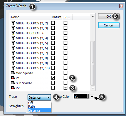
Figure 1 - Select a Datum, Reference, trace mode, and color in Create Watch.
Step 4 - Run and Analyze the Watch
Rewind Machine Simulation to the start of the sequence.
Play the simulation. The location values in the Watches dialog update continually during rendering.
For a Path Watch, follow the colored trace in the workspace and review the point's motion history.
For a Distance Watch, review the colored line and axis blocks connecting Datum and Reference while monitoring the location values.
Pause or step through the simulation around critical motion so the value, direction, and machine position can be inspected.
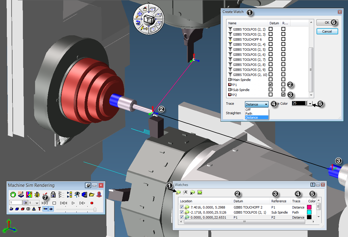
Figure 2 - Multiple Watches displaying Path and Distance traces during Machine Simulation.
Step 5 - Manage and Reuse Watches
Create additional Watches when several relationships must be compared. Assign a different Trace Color to each enabled Watch.
Select or clear the checkbox beside a Watch to enable or disable it without deleting its definition.
Double-click a Watch in the list to edit its Datum, Reference, Trace mode, or color.
Use the import and export controls in the Watches dialog to save or load Watch definitions as .smd files.
After changing the machine model, part offset, operations, or Watch definitions, reload or rewind Machine Simulation and repeat the review.
Expected Result
The Watch appears in the Watches dialog with the intended Datum, Reference, trace mode, and color. After Machine Simulation is rewound and played, the location values update continuously. Path Watches leave a colored motion trace, while Distance Watches display a colored connecting line with axis blocks at both ends.
Additional Information
Watches are available only in Machine Simulation, not Rapid, Op, or Tool Simulation.
Datum and Reference can be assigned to almost any item defined in the current Machine Model.
Multiple Watches can be displayed at the same time. Use distinct colors and disable unneeded Watches to keep the display readable.
A Watch can remain defined with Trace set to Off. Its visibility can also be controlled with the checkbox in the Watches list.
Path Trace lines use the selected color. Distance lines also display an axis block at each end.
Watch definitions can be imported and exported as .smd files.
Source documentation: GibbsCAM 2026 Machine Simulation, Using Machine Simulation > Simulation Context Menus > Watches, pages 55-56.
Troubleshooting
Problem: Watches is not available from the Simulation controls.
Possible Causes
The active mode is Rapid, Op, or Tool Simulation rather than Machine Simulation.
The Machine Sim Rendering context menu was not opened from its title bar.
A valid Machine Simulation model is not selected or loaded.
Resolution
Switch the Sim control to Machine Sim, select the correct machine model, and reload the simulation. Right-click the Machine Sim Rendering title bar and select Watches.
Problem: The required Datum or Reference is not listed.
Possible Causes
The wrong Machine Simulation model is active.
The required component, tool position, touch-off point, spindle, or other item is not defined in the current Machine Model.
The selected machine assembly does not match the active MDD or setup.
Resolution
Confirm the active MDD and machine model. Select the correct assembly and reload Machine Simulation. If the required point is still absent, have the machine model reviewed and corrected before relying on the Watch.
Problem: The Watch exists, but no line appears or the values do not update.
Possible Causes
The Watch checkbox is cleared or Trace is set to Off.
Machine Simulation was not rewound and played after the Watch was created.
The selected Datum and Reference do not move relative to one another during the reviewed sequence.
Resolution
Enable the Watch, choose Path or Distance, rewind the rendering, and play the applicable operations. Verify that the selected points are expected to move relative to each other.
Problem: The reported location or direction is not the expected measurement.
Possible Causes
Datum and Reference were reversed or the wrong model items were selected.
The active part offset, machine model, tool position, or setup does not match the intended configuration.
The Watch is being interpreted as a physical clearance without confirming the selected point definitions.
Resolution
Edit the Watch and confirm both selected items. Reverse Datum and Reference when needed, verify the part offset and setup, reload the simulation, and compare the Watch result with known machine-model positions before using it for analysis.
Problem: Multiple Watch traces are difficult to interpret.
Possible Causes
Several Watches use the same or similar Trace Color.
Too many Watches are enabled at the same time.
Old Path traces remain visible from an earlier playback.
Resolution
Assign distinct colors, disable Watches that are not part of the current question, rewind or reload the simulation, and replay only the operation sequence required for the analysis.
Related Articles
Explore More from CAMCO
Visit the CAMCO website to learn more about:
Keywords
GibbsCAM, Watches, Set Watches, Machine Simulation, Machine Sim, Datum, Reference, Path Trace, Distance Trace, Trace Color, Watch Location, SMD File, Simulation Diagnostics, Machine Model