
Summary
Facet bodies are triangulated models that GibbsCAM can query, profile, slice, and machine in supported workflows. They may come from an imported STL or GibbsCAM Facet Body file, from a solid-to-facet conversion, or from the Create Facet Body command in Cut Part Rendering.
This article explains how to prepare a facet body, assign the correct body role, select it in a compatible machining process, define toolpath stock separately, and verify the finished operation. It also explains the critical limitation that a facet body assigned as stock is display-only and does not become the stock condition used to create toolpath.
Table of Contents
- Before You Begin
- Facet Body Roles and Toolpath Behavior
- Procedure
- Best Practices
- Troubleshooting
- Related Articles
Before You Begin
Use an imported or created facet body that accurately represents the surfaces or features required for machining.
Confirm the body units, scale, orientation, coordinate system, and position before creating any operations.
Verify that the selected machining process and installed GibbsCAM version support facet-body input for the required role.
Keep the original CAD model when it is available. A facet body stores triangles rather than analytic faces, feature history, or parametric design data.
Save a working copy of the GibbsCAM part before healing, smoothing, simplifying, re-faceting, transforming, or reclassifying a body.
Establish the actual stock condition, fixtures, toolholders, and clearance strategy required for safe toolpath and simulation verification.
Important: A facet body can be machined when the selected process supports it, but a facet body assigned as Stock or Stock - Display Only is not used as the stock condition for generating toolpath. Use a supported stock definition for stock-aware calculation and use facet stock for display or simulation reference.
Facet Body Roles and Toolpath Behavior
Choose the body role before programming. The same triangulated body can behave differently depending on how it is classified and how the machining process uses it.
Procedure
Step 1 - Create or Import the Facet Body
Use one of the following methods to place a facet body in the current GibbsCAM part:
Imported mesh: Select File > Import and choose STL (*.stl), GibbsCAM Facet Body (*.fb), or GibbsCAM Facet Body (v2) (*.fb2), as available in the installed version.
Rendered condition: Run Cut Part Rendering to the required condition, open the Simulation context menu, and select Create Facet Body.
Converted solid: Use the Facet Body Solid Modeling tools when a supported B-rep body must be tessellated for the workflow.
Confirm that the new body appears in the workspace or Body Bag. Facet bodies normally display with transparency.
Rename the body so its role is clear, such as Facet Part, Fixture Mesh, or Op 2 Display Stock.
Expected Result
A clearly named facet body is available in the current GibbsCAM part.
Step 2 - Inspect and Prepare the Mesh
Measure one or more known features to verify the imported scale and units.
Rotate and inspect the body for missing regions, disconnected components, inverted facets, unwanted shells, or an excessively coarse surface.
Confirm the work coordinate system and reposition the body only from known datums or model values.
In GibbsCAM 2025 and later, use the Facet Body Solid Modeling palette to Heal, Smooth, Simplify, Re-facet, Tesselate, Slice, Separate, Boolean, or Offset/Shell only as required by the model and operation.
Recheck critical dimensions and surfaces after every repair, simplification, or transformation.
Expected Result
The facet body is correctly scaled, positioned, and detailed enough for the intended machining selection.
Step 3 - Assign the Intended Body Role
Open the facet body's Properties dialog from the workspace or Body Bag.
For machining input, assign the body as Part or the supported role required by the selected process.
Use Fixture or machine-component roles only when the body is meant to provide setup or simulation context.
If Stock or Stock - Display Only is selected, treat the body as visible simulation stock, not as the stock condition that will drive toolpath generation.
Expected Result
The body classification matches how the facet body will be used by machining and simulation.
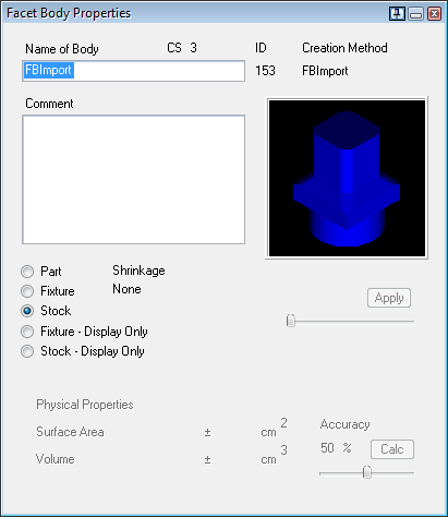
Figure 1 - Facet Body Properties includes Part, Fixture, Stock, and display-only body roles.
Step 4 - Select the Facet Body in a Supported Process
Create or open the machining process that will generate the toolpath.
Verify that the process accepts a facet body for the required part, surface, or machining selection. Commands and selection methods vary by GibbsCAM product and release.
Set the tool, coordinate system, feature depth or surface limits, containment, clearance, feeds, speeds, and remaining process parameters.
Select the facet body or the required faceted region as the machining input. If direct selection is not supported, use an alternative supported process or extract suitable geometry from an available solid model.
Create or recalculate the operation, then inspect the displayed toolpath before simulation.
Expected Result
The operation calculates and the toolpath follows the intended faceted machining input.
Step 5 - Define Toolpath Stock Separately
Determine whether the selected operation uses stock-aware calculation, Material Only behavior, rest material, or another remaining-stock control.
Define the calculation stock with a supported stock method, such as Stock Wizard stock, workgroup geometry, a supported B-rep solid, or the operation's documented stock input.
Keep any facet body assigned as stock visible only when it helps communicate an imported or in-process condition during rendering.
Regenerate the operation after changing the calculation stock or machining selections.
Expected Result
The operation uses a supported stock condition for calculation while the facet stock, if present, remains a clear simulation reference.

Figure 2 - Example of a faceted body used to display an in-process stock condition.
Step 6 - Verify the Toolpath and Simulation
Backplot or inspect the operation from multiple views, paying close attention to coarse facets, open regions, boundaries, rapid moves, and clearance around fixtures.
Run Cut Part Rendering or Op Simulation with the intended part, stock, fixtures, tool, and holder visible.
Run Machine Simulation when machine-axis motion, limits, holder reach, or machine-component collisions must be checked.
Compare the result with the source model and the intended remaining material. Correct selections, stock, tolerances, or setup positioning and regenerate as required.
Review the posted CNC program and complete the shop's normal setup and prove-out process before production.
Expected Result
A compatible GibbsCAM process generates toolpath from the intended facet body or faceted region. The body is correctly scaled, positioned, and classified, while any stock used for stock-aware calculation is defined through a supported stock method rather than relying on display-only facet stock. The regenerated operation and simulation have been reviewed before posting or release.
Best Practices
Use the lowest facet density that preserves every surface, edge, and feature important to the operation; unnecessary facets increase file size and calculation time.
Request the original Parasolid, STEP, or other supported B-rep model when analytic faces, editable design features, or a process unsupported by facet bodies is required.
Name and organize facet bodies by purpose so programmers can distinguish part geometry, fixtures, machine components, and display stock.
Verify the model scale immediately after import because STL files do not reliably identify source units.
Treat mesh repair and simplification as controlled changes; inspect the model again before recalculating toolpath.
Confirm compatibility with the specific process. For example, GibbsCAM Mill documentation states that Deburr/Chamfer does not support facet bodies or sheets.
Do not use Solid to Facet Body Conversion Tolerance as a machining-accuracy setting; GibbsCAM documents it as a CAD-conversion tolerance, while machining and display use separate tolerances.
Verify toolpath, simulation, posted output, offsets, clearances, and workholding using the shop's normal release procedure.
Troubleshooting
Problem: The machining process will not accept the facet body.
Possible Causes
The selected process does not support facet-body input for the requested role.
The body is classified as Stock, Fixture, or display-only instead of the required machining role.
The installed GibbsCAM version or license does not include the required process or facet-body function.
Resolution
Verify the process documentation and body classification. Use a supported process, change the body to the correct role, or obtain a supported B-rep model. Do not assume that every solid-based command accepts facet bodies; Deburr/Chamfer is one documented exception.
Problem: The toolpath ignores the facet body assigned as stock.
Possible Causes
Facet stock is display-only and is not the stock condition used to create toolpath.
The operation's Material Only, rest-material, containment, or stock input is defined elsewhere.
Resolution
Define toolpath stock with a supported stock method for the selected operation. Keep the facet stock only as a rendering or in-process visual reference, then regenerate and inspect the operation.
Problem: The toolpath looks faceted, incomplete, or inaccurate.
Possible Causes
The source mesh is too coarse for the required surface detail.
The facet body contains gaps, damaged regions, disconnected shells, or unwanted triangles.
The wrong body, region, coordinate system, boundary, or machining limits were selected.
Resolution
Inspect the mesh and selection closely. Repair or re-facet the model when appropriate, request a higher-quality export or B-rep model when needed, confirm the active coordinate system and limits, and regenerate the operation.
Problem: The file or operation becomes slow after importing the mesh.
Possible Causes
The model contains far more facets than the machining task requires.
Several duplicate or hidden facet bodies remain in the part.
A repair, smoothing, or re-facet setting created excessive mesh density.
Resolution
Remove unneeded bodies, simplify or re-export the mesh at a practical resolution, and retain only the detail required for machining and verification. Save a copy before reducing facet density.
Problem: The facet body is difficult to see or select.
Possible Causes
Facet Body Opacity is set too low.
The body is hidden, on a different Body Bag page, or coincident with another body.
The active body, face, or edge selection mode does not match the intended selection.
Resolution
Adjust Facet Body Opacity in Display preferences, show the correct Body Bag page, temporarily hide overlapping bodies, and activate the selection mode required by the process.
Additional Information
The official GibbsCAM Common Reference and Machine Simulation documentation states that facet bodies can be queried, profiled, sliced, and machined. The same documentation states that a facet body set as stock can be shown in rendering but is not used as a stock condition for creating toolpath.
GibbsCAM 2025 expanded facet-body modeling with Tesselate, Simplify, Re-facet, Heal, and Smoothing commands, and extended several solid-modeling functions to facet bodies. Available commands and machining-process support can vary by product, license, and release.
Related Articles
- Utilizing STL Models in GibbsCAM
- Extracting Geometry from Solids
- Recommended Simulation Settings
- Solid Model Looks Distorted
Explore More from CAMCO
Visit the CAMCO website to learn more about:
Keywords
GibbsCAM, Facet Body, Faceted Body, Mesh, STL, FB, FB2, Toolpath, Machining Facet Bodies, Part Body, Display Stock, Stock Display Only, In-Process Stock, Material Only, Facet Body Solid Modeling, Tesselate, Simplify, Re-facet, Heal, Smoothing, Cut Part Rendering, Create Facet Body, Deburr Chamfer