
Summary
This article explains how to change a GibbsCAM part between inch and metric units in the Document Control dialog (DCD), how that change affects existing geometry and solid models, and when to use Scale to preserve the intended physical size.
Table of Contents
Before You Begin
Save a backup copy of the part before changing units, especially if it already contains geometry, tools, or operations.
Confirm whether you only need to change the document's working units or whether existing content must be physically converted between inch and metric.
Important: Changing the DCD unit setting reinterprets existing geometry and toolpath values in the selected unit. It is not the same as scaling those values to preserve their physical size.
How Unit Changes Affect Existing Data
Geometry and toolpath values: The numeric values remain the same, but GibbsCAM interprets them in the newly selected unit. For example, a line with a length of 2 mm becomes a 2-inch line when the part changes from millimeters to inches.
Solid models and sheets: These retain their physical size because their model data contains unit information. Their size may appear to change relative to wireframe geometry after the DCD units are switched.
Mixed geometry and solids: A mismatch is easiest to see when both are present. For example, after changing an inch part to millimeters, a 2-inch solid remains 2 inches while 2-unit wireframe geometry is interpreted as 2 mm, making the solid appear much larger by comparison.
Procedure
Step 1 - Change the Document Units
Open the GibbsCAM part.
Select the Document button to open the Document Control dialog (DCD).
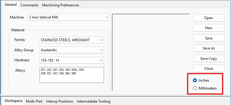
Under Unit of Measurement, select Inch or Millimeter (MM), then close the DCD and review the part in the workspace.
Step 2 - Scale Existing Content if Required
Measure a known feature and determine whether the geometry already has the intended physical size.
If a physical conversion is required, select only the geometry or bodies that need to be resized.
Select Modify > Transform > Scale. In older GibbsCAM releases, select Modify > Scale.
Apply the corresponding inch-to-millimeter or millimeter-to-inch conversion. If a scale factor is required, use 25.4 for inch to millimeter or 0.0393700787 for millimeter to inch.
Measure the converted content again to confirm its size.
Version note: In GibbsCAM 2026 and later, Scale supports 2D geometry, solid bodies, facet bodies, and sheets. In earlier releases, Scale applies to 2D geometry. Do not scale a correctly sized solid simply because the DCD units changed.
Step 3 - Verify Programming Data
Review the stock dimensions, part origin, clearances, tools, process settings, and operation values for the selected unit system.
Recalculate or regenerate affected toolpaths.
Run Cut Part Rendering or Simulation and verify the toolpath before posting the program.
Save the part after all dimensions and toolpaths have been verified.
Expected Result
The part uses the selected inch or metric unit system, the geometry and solid model have the intended physical size, and all affected programming data and toolpaths have been verified.
Related Articles
Explore More from CAMCO
Visit the CAMCO website to learn more about:
Keywords
Inch, Metric, Millimeter, MM, Unit of Measurement, Document Control Dialog, DCD, Unit Conversion, Scale, Scale Factor, 25.4, Geometry, Solid Model, Toolpath, GibbsCAM Units