
Summary
This article explains how to create and import an OptiThreading tool assembly from Sandvik Coromant's CoroPlus Tool Library, use its recommended cutting data in a GibbsCAM Thread process, and verify the resulting oscillating toolpath. OptiThreading was introduced in GibbsCAM 2025 to create controlled chip-breaking interruptions during thread turning while leaving the final pass continuous.
Table of Contents
Before You Begin
Use GibbsCAM 2025 or later with the required Turning capability and an appropriate machine definition.
Confirm that the workstation has internet access and that you can sign in to an active CoroPlus Tool Library subscription.
Know the workpiece material, thread type, nominal diameter, pitch, length, hand, tolerance, and whether the thread is internal or external.
Confirm the physical toolholder, insert, turret location, insert orientation, and machine clearances before creating the assembly.
Use an approved post processor for the target machine and retain a backup copy of the GibbsCAM part before changing a production process.
Important: CoroPlus recommendations and the displayed OptiThreading controls are programming inputs, not a substitute for tool-manufacturer limits, machine limits, posted-code review, or the shop's prove-out procedure.
Procedure
Step 1 - Open CoroPlus Tool Library
Open the GibbsCAM part and confirm the active machine, stock, part units, and thread location.
Select Plug-Ins > Main Tools > CoroPlus Tool Library.
Sign in with the CoroPlus account when prompted and wait for the CoroPlus Tool Library Importer to load.
Click New Assembly.
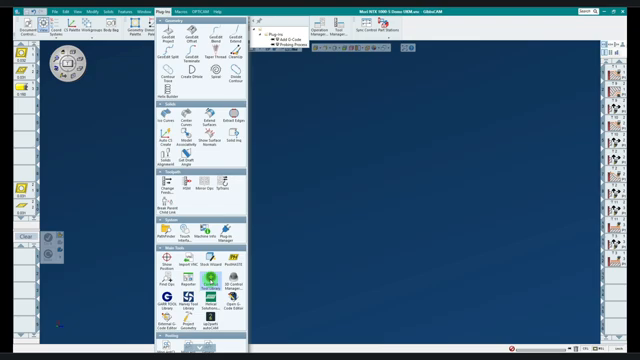
Figure 1 - Open CoroPlus Tool Library from the GibbsCAM Plug-Ins palette.
Step 2 - Build the Threading Tool Assembly
In the CoroPlus catalog, choose the turning and thread-turning application that matches the required internal or external thread.
Filter the holder by the required direction, shank size, and other machine or setup constraints, then select the holder.
Add a compatible threading insert to the assembly. Use filters such as pitch or threads per inch and thread form when applicable.
Review the holder and insert connection, overhang, orientation, and assembly dimensions.
Enter a clear Name and, when useful, a Description and Classification for the assembly.
Click Save. Saving the assembly makes its Cutting Data tab available.
Step 3 - Add OptiThreading Cutting Data
Open the Cutting Data tab and select Get Recommendations. Use Specify Own Cutting Data only when approved values are available.
Select the workpiece material, internal or external threading task, and the applicable machine-size or working-condition options.
Choose a supported thread standard or define a custom thread that matches the part requirements.
Enter the nominal diameter, thread length, hand, tolerance, and other requested thread parameters. Follow the units displayed beside each field.
Turn the OptiThreading enabled toggle on.
Click Get Results, review the recommendation, and click Apply.
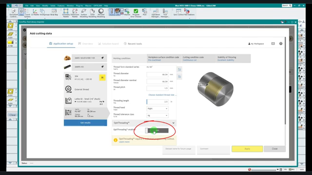
Figure 2 - Enable OptiThreading in the CoroPlus cutting-data recommendation.
Step 4 - Send the Assembly to GibbsCAM
Click Send to GibbsCAM after the cutting data has been applied.
Select the insert direction or orientation that matches the actual turret, tool station, spindle, and approach direction, then click OK.
Wait for GibbsCAM to add the tool and build the imported assembly.
Minimize or close the CoroPlus window and open the imported tool in GibbsCAM.
Verify the insert, holder, tool block, orientation, toolgroup, and dimensional data before using the tool.
Step 5 - Create the OptiThreading Process
Place the imported tool on an empty Process tile and select a Thread process.
Under Definition, select From Cutting Data. This choice appears only when the selected tool contains compatible cutting data.
Verify the imported thread type and direction, thread length, pass count, diameters, pitch, and start location against the part requirements.
Review Oscillation Frequency, Oscillation Extra Lift Distance, and Extra Oscillation Final Rough Pass. Keep the recommended values unless a controlled test supports a change.
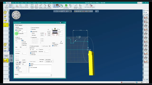
Figure 3 - Select From Cutting Data in the GibbsCAM Thread process.
Step 6 - Generate and Verify the Toolpath
Click Do It to generate the operation.
Zoom in on the thread toolpath and confirm that the roughing passes contain the expected oscillating interruptions.
If an approved change is required, adjust the Oscillation Extra Lift Distance or another OptiThreading control, regenerate, and compare the result. A larger extra-lift value creates a more pronounced lift movement.
Run Op Simulation and, when applicable, Machine Simulation with the tool, holder, stock, fixtures, and collision checking enabled.
Post the operation with the approved machine post and inspect the complete NC output, including spindle synchronization, feed, approach, retract, oscillating motion, and the final pass.
Complete the shop's normal single-block, dry-run, and machine prove-out procedure before production use.
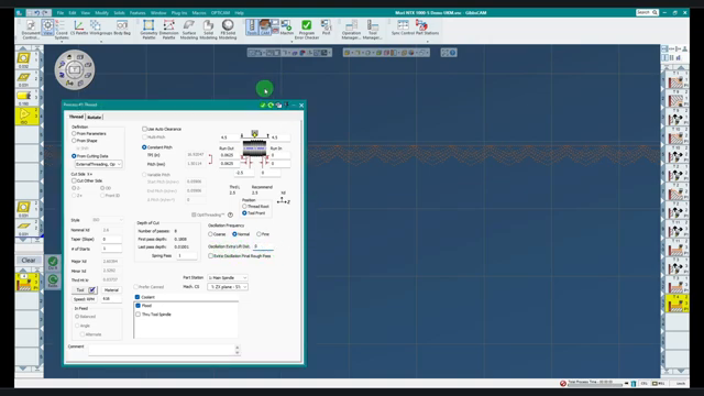
Figure 4 - Generated OptiThreading toolpath with visible oscillating lift movements.
Expected Result
The CoroPlus threading assembly appears in the GibbsCAM Tool list with compatible recommended cutting data. The Thread process offers From Cutting Data, generates the expected OptiThreading oscillations on the roughing passes, and produces verified NC output for the approved machine and post processor.
Related Video
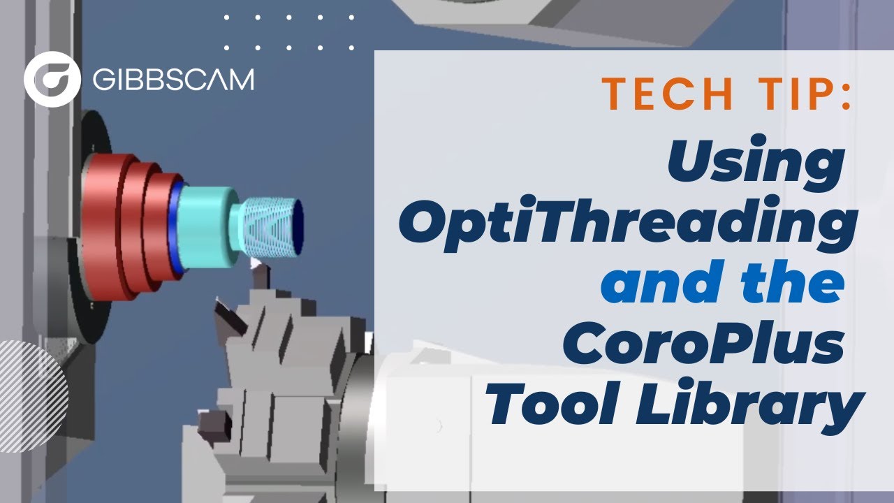
Additional Information
OptiThreading uses controlled in-and-out oscillating movement to create repeated interrupted cuts on all passes except the final pass. The interruptions are intended to improve chip breaking during thread turning.
OptiThreading is especially useful when long chips interfere with the tool or workpiece, and for demanding thread profiles, high-strength or exotic materials, or applications with strict surface-finish requirements.
Oscillation Frequency changes the density of the oscillation pattern. Oscillation Extra Lift Distance changes how far the tool lifts beyond the base oscillation. Extra Oscillation Final Rough Pass applies oscillation to the final roughing pass when enabled.
CoroPlus may display different units for different thread fields. Read the unit label beside each value and convert the part dimensions before entry when necessary.
The CoroPlus catalog and recommendation interface can change over time; follow equivalent task, workpiece, thread, and OptiThreading controls when labels or placement differ.
Troubleshooting
Problem: From Cutting Data is not available in the Thread process.
Possible Causes
The selected tool was not imported from CoroPlus with compatible recommended cutting data.
OptiThreading was not enabled before Get Results and Apply were selected.
A different tool is selected, or the current GibbsCAM release predates OptiThreading support.
Resolution
Return to CoroPlus, verify the compatible holder and insert, enable OptiThreading in the cutting-data setup, apply the result, and send the assembly to GibbsCAM again. In GibbsCAM 2025 or later, select the newly imported tool in a Thread process.
Problem: The Cutting Data tab or OptiThreading recommendation is unavailable in CoroPlus.
Possible Causes
The assembly has not been saved.
The CoroPlus subscription or login is inactive.
The holder, insert, material, task, or thread definition is incomplete or incompatible with OptiThreading.
Resolution
Save the completed assembly, confirm the active CoroPlus account, and define a compatible threading task, workpiece material, holder, insert, and thread. Then open Cutting Data and request recommendations again.
Problem: The generated path does not show the expected oscillations or appears too aggressive.
Possible Causes
From Cutting Data is not selected or the operation was not regenerated after a parameter change.
The view is too far from the thread to make the oscillations visible.
Oscillation Frequency or Oscillation Extra Lift Distance is not appropriate for the intended application.
Resolution
Select From Cutting Data, regenerate the operation, and zoom in on the toolpath. Compare the current frequency and extra-lift values with the imported recommendation. Make only an approved change, then regenerate, simulate, post, and prove out the result.
Problem: The operation simulates but the post fails or the NC output is unexpected.
Possible Causes
The post processor does not support the operation data or current GibbsCAM release.
The wrong machine, post processor, tool orientation, or thread direction is active.
A post-specific limit or output rule changes the generated motion.
Resolution
Verify the active machine, post, tool orientation, thread direction, and operation data. Reproduce the problem with the approved post and provide the part and post details to the post developer or CAMCO Technical Support. Do not run unverified output on the machine.
Related Articles
- How to Save and Load Process or Tool Lists
- Recommended Simulation Settings
- Error: "Fatal Post Error"
- How to Create a Pack and Go File
Explore More from CAMCO
Visit the CAMCO website to learn more about:
Keywords
OptiThreading, GibbsCAM 2025, CoroPlus Tool Library, CPTL, Thread Turning, From Cutting Data, Oscillation Frequency, Extra Lift Distance, Chip Breaking, Threading Tool, GTC Package, Sandvik Coromant