
Summary
Utility Markers let you change position-dependent data at specific locations in an existing GibbsCAM toolpath. They can change feed rate, spindle speed, tool offset, cutter radius compensation (CRC), dwell, program stop, or posted text; supported turning machines can also use a Tool Sub Position marker. Because several marker types depend on the post processor, always verify the regenerated operation, simulation, and posted NC output before machining.
Table of Contents
Before You Begin
Create and review the operation first. Utility Markers modify position-dependent data on finished toolpath; they do not replace the process definition or correct an invalid toolpath.
Save a backup of the part before editing markers on a production operation.
Identify the exact toolpath location where the change should begin and where the original state should be restored.
Confirm the active tool, offset numbers, units, spindle mode, CRC strategy, and any machine-specific tool sub positions.
Confirm that the approved post supports the intended marker. Variable Feed Rate and CRC are documented without the special post-support requirement; other marker types require specific post logic.
Important: A marker can change posted machine behavior even when the underlying toolpath geometry looks unchanged. Do not rely on the marker icon or GibbsCAM display alone—inspect the posted code and complete the normal prove-out procedure.
Procedure
Step 1 - Open Utility Markers for an Operation
In the Operation List, select the completed Mill or Turning operation to edit.
Right-click the operation tile and select Utility Markers.
Enable Show All Markers when you need to see every marker type already placed on the operation.
Use Previous Marker and Next Marker to move through existing markers. The dialog updates to show the selected marker's position and properties.

Figure 1 - Utility Markers dialog with Variable Feed Rate selected.
Step 2 - Choose the Marker Type and Value
Open Marker Type and select the required marker.
Set the marker-specific option or value. For example, choose User, Entry, Contour, Percent, or Max for Variable Feed Rate; enter text for a Text marker; or choose M0/M1 behavior for Program Stop.
For a Tool Offset marker, confirm whether the operation should use the tool offset, deflection-compensation offset, or an explicit offset number.
For Dwell, choose Seconds or Revolutions. A revolutions-based dwell uses the current spindle speed to calculate time.
Step 3 - Place the Marker on the Toolpath
Drag the marker icon from the dialog to the exact position on the toolpath where the change should begin.
Confirm that the selected marker appears red and that the displayed X, Y, Z, and Feature values correspond to the intended toolpath location.
Zoom in and inspect the surrounding toolpath. Reposition the marker if it attached to the wrong feature or side of a corner.
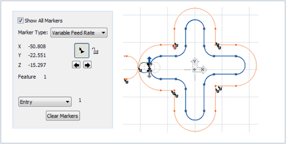
Figure 2 - Variable feed markers placed around filleted toolpath regions.
Step 4 - Define the End of a Temporary Change
If the change should apply only to part of the toolpath, place another appropriate marker where the original state should resume.
For a temporary feed reduction, place the first Variable Feed Rate marker before the feature and a second marker after it to restore Contour, Entry, User, or another approved feed state.
For CRC, spindle, offset, dwell, or stop changes, use the marker sequence required by the approved post and machine control.
Step through the markers in toolpath order and confirm that each transition is positioned on the intended feature.
Step 5 - Lock the Intended Marker Values
Use the graphical lock control beside the marker value to toggle between locked and unlocked.
Lock values that must remain after reprocessing. A small lock symbol appears on the Operation tile when the operation contains one or more locked values.
Leave a value unlocked only when it should return to its original value if the operation is reprocessed.
Reprocess the operation when necessary, then reopen Utility Markers and confirm the required markers and values remain.
Step 6 - Verify the Result
Inspect the toolpath drawing and rendered image for changes that affect the operation.
Run the appropriate operation and machine simulation, including the tool, holder, stock, fixtures, and collision checking.
Post the operation with the approved machine post and locate every expected feed, speed, offset, CRC, dwell, stop, text, or sub-position output change.
Check that each change begins and ends on the intended NC block and that no required restoration marker is missing.
Complete the shop's standard single-block, dry-run, and machine prove-out procedure before production use.
Marker Type Reference
Post-processor requirement: Except for Variable Feed Rate and CRC, the GibbsCAM references state that marker types require specific post-processor support. Contact CAMCO Technical Support before relying on unsupported or unverified marker output.
Expected Result
The operation contains markers at the intended toolpath locations, the required locked values survive reprocessing, and the approved post outputs each feed, speed, offset, CRC, dwell, stop, text, or turning sub-position change on the expected NC block.
Related Video

Additional Information
Show All Markers displays icons for all marker types. Each type has a unique icon; selecting Previous Marker or Next Marker updates the dialog to the highlighted marker.
Clear Markers removes all Utility Markers from the selected operation. Use it only when the complete marker set should be deleted.
Changes that affect the toolpath appear in the toolpath drawing and rendered image. The process tile that created the operation is modified to reflect changes made in the Utility Markers dialog.
Tool Sub Position is documented only for turning machines that support sub positions. It is not a general Mill marker.
The Variable Feed Rate Percent option uses the last fixed feed-rate marker as its basis. Review the marker order before using multiple percentage changes.
Source documentation: GibbsCAM 2026 Mill Reference, Utility Markers, pages 160-162; and GibbsCAM 2026 Turning Reference, Utility Markers, pages 109-111.
Troubleshooting
Problem: The marker appears in GibbsCAM, but the expected code is missing from the posted program.
Possible Causes
The selected marker type is not supported by the active post processor.
The wrong post, machine, or operation was posted.
The marker is attached to a different feature than expected or is outside the posted operation range.
The post uses a machine- or control-specific output rule for the selected marker.
Resolution
Confirm the active machine, post, operation, marker type, and marker position. Post a small controlled test and inspect the complete output. If the marker is not recognized, provide the part, post, expected output, and actual output to CAMCO Technical Support for post review.
Problem: A feed, speed, CRC, or offset change starts or ends at the wrong location.
Possible Causes
The marker was dropped on the wrong toolpath feature or side of a corner.
A second marker that restores the original state is missing or misplaced.
Several markers are stacked closely together and were reviewed out of sequence.
Resolution
Zoom in, reopen Utility Markers, and use Previous Marker and Next Marker to inspect the markers in order. Move the first marker to the exact start feature and add or reposition the restoration marker. Repost and confirm the affected NC blocks.
Problem: Marker values disappear or return to their original values after reprocessing.
Possible Causes
The marker value was left unlocked.
The operation was regenerated from a process that does not preserve the intended unlocked change.
The entire marker set was cleared or the operation was recreated.
Resolution
Reopen Utility Markers, re-enter the approved value, and set its lock control to locked. Confirm the lock symbol appears on the Operation tile, reprocess the operation, and verify that the marker and value remain.
Problem: The Tool Sub Position marker is unavailable.
Possible Causes
The selected operation is not a turning operation.
The active turning machine definition does not allow tool sub positions.
The active post or machine configuration does not support the requested sub-position output.
Resolution
Confirm that the part uses the correct turning MDD and a toolgroup that supports sub positions. If the machine should support the function but the marker remains unavailable, have CAMCO review the MDD and post configuration before programming around the limitation.
Related Articles
- Recommended Simulation Settings
- Accurate Cut Time Calculation
- Error: "Fatal Post Error"
- How to Create a Pack and Go File
Explore More from CAMCO
Visit the CAMCO website to learn more about:
Keywords
Utility Markers, GibbsCAM, Variable Feed Rate, Spindle Speed, Tool Offset, CRC, Cutter Radius Compensation, Dwell, Program Stop, M0, M1, Tool Sub Position, Text Marker, Lock Marker, Toolpath, Post Processor