
Summary
This article provides best practices for defining, selecting, and validating Mill and Turning form tools in GibbsCAM. A reliable form-tool workflow starts with the simplest accurate tool definition, clean profile geometry, a deliberate origin or touch-off point, correct cutting and non-cutting attributes, and a contact model that matches the cutter manufacturer's programming data. These checks help prevent unexpected toolpath offsets, collisions, slow calculation, and differences between the rendered cutter and posted motion.
Before You Begin
Obtain the cutter manufacturer's current drawing or DXF, nominal diameter, programming radius when supplied, holder and stickout dimensions, and recommended cutting data.
Use a standard GibbsCAM tool type when it fully represents the cutter. Use a form tool when the custom cutting shape is necessary for toolpath calculation or verification.
Keep imported tool geometry in a separate workgroup, remove dimensions and annotation, and save a backup of the part before replacing an existing tool definition.
Confirm whether the tool is a Mill 2D Form, Mill 3D Form, or Turning form tool before preparing geometry; their source-shape and origin requirements differ.
Important: A correct rendered shape does not by itself prove a safe toolpath. Verify the profile, contact model, origin or touch-off point, holder and stickout, operation depths, simulation results, and posted output before machining.
Choose the Correct Form Tool Type
Best Practices
Step 1 - Start with the Simplest Accurate Tool Definition
Compare the cutter with the available standard GibbsCAM tool types before creating a form tool.
Choose the correct Mill or Turning form-tool type only when the cutter's custom profile must affect toolpath calculation or verification.
Build the definition from authoritative manufacturer data rather than a catalog illustration or a rendered preview alone.
Record the nominal diameter, programming radius or Virtual Corner Radius when provided, holder, stickout, and intended operations so the definition can be audited later.
Step 2 - Build Clean Source Geometry
Remove dimensions, centerlines, duplicate entities, the holder, and any insert geometry that will not participate in cutting.
For a Mill 2D Form tool, keep one connected, open, terminated profile around X0. Only connected geometry is used when the form tool is applied.
For a Turning form tool, create a closed shape and avoid concave regions unless the concavity is actually used to remove material.
Chain-select the profile and repair gaps, overlaps, branches, or unintended extra segments before applying it to the tool tile.
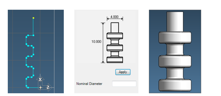
Figure 1 - Verify that the selected Mill profile, loaded tool diagram, and rendered form tool agree.
Step 3 - Set the Origin and Touch-Off Deliberately
For a Mill 2D Form tool, position the profile around X0 and use the intended tool-tip reference at the source coordinate-system origin.
For a Turning form tool, place the source coordinate-system origin at the intended touch-off point. GibbsCAM shows this point as a red cross in the tool diagram, and posted output is relative to it.
Exclude unused turning-tool geometry that extends above the touch-off point; it can change the calculated path and create a collision.
Recheck the origin after importing, translating, scaling, or rotating source geometry.
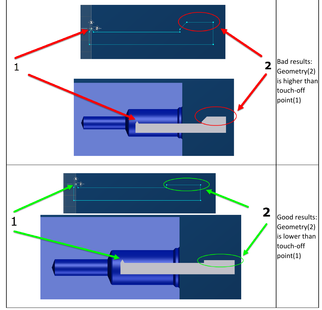
Figure 2 - For Turning form tools, keep unused profile geometry from extending above the touch-off point.
Step 4 - Separate Cutting and Non-Cutting Geometry
Keep only geometry needed to describe the cutter's functional shape. Define the holder and other assembly components with the appropriate holder or tool specifications instead of adding them to the cutting profile.
Leave cutting segments classified as Wall and change non-cutting profile segments from Wall to Air.
Review every transition between Wall and Air so a shoulder, neck, pilot, or relief is not accidentally treated as a cutting edge.
Apply or regenerate the tool, then compare the diagram and rendered tool with the manufacturer drawing.
Step 5 - Choose the Mill Contact Model
For a Mill 2D or 3D Form tool, open Generate toolpath from and choose the model that matches the actual programming method.
Use Real profile when the actual form, including required undercut behavior, must determine contact points and the additional calculation time is acceptable.
Use Monotonic profile when undercutting should be disabled to preserve shank clearance as the tool narrows.
Use Nominal parameters only when the manufacturer supplies a nominal diameter and simplified programming radius; enter and verify the Virtual Corner Radius before generating operations.

Figure 3 - Choose the Mill form-tool contact model that matches the cutter and manufacturer programming data.
Step 6 - Control Profile Complexity and Tolerance
Use clean lines, arcs, and only the splines needed to represent the cutting shape. Avoid tracing noise and excessive short entities.
Review DCD > Machining Preferences > Spline Machining Tolerance because the setting is used by both 2D and 3D Form tools.
Use a tolerance appropriate for the part and cutter. An unnecessarily tight tolerance can increase calculation and cut-part rendering time; a tolerance that is too loose can change the fitted shape and contact result.
For Material Only operations, use constant- or decreasing-radius tools when possible. GibbsCAM does not recognize undercuts in Material Only; increasing-radius, mushroom, or undulating form tools can produce air cutting or unsafe rapid motion.
Step 7 - Verify Depth, Simulation, and Posted Output
For Mill 2D operations, confirm Surface Z and Final Depth. GibbsCAM offsets the form tool as though the geometry is at the top surface and the tool is at final depth.
Confirm tool orientation, nominal dimensions, holder, stickout, spindle assignment, and clearance before regenerating the operation.
Run operation simulation and Machine Simulation, inspecting the actual tool profile, non-cutting regions, holder clearance, entry and exit motion, and remaining stock.
Review the posted coordinates and compensation method against the setup and manufacturer programming data. A Turning form tool has no tip radius, so tool edge path is unavailable.
Use the approved post processor and follow the shop's standard prove-out procedure before production machining.
Expected Result
The tool diagram and rendered cutter match the manufacturer definition, the toolpath contacts the intended cutting region, non-cutting features and the holder remain clear, simulation shows the expected stock removal, and the posted output uses the intended origin, touch-off point, and compensation method.
Additional Information
The Mill Generate toolpath from selection changes contact-point calculation. Material Only and rendering use the Real profile whenever possible.
Mill 2D Form tools are intended for supported 2D milling and are not compatible with 3D milling.
Complex form-tool profiles can slow cut-part rendering. Simplify geometry without changing the functional cutting shape.
If the manufacturer's nominal diameter is smaller than the maximum diameter calculated from a Mill form-tool profile, enter the manufacturer's nominal value in the Nominal Diameter field.
Turning form tools do not have a tip radius; tool edge path is therefore unavailable for these tools.
Source documentation: GibbsCAM 2026 Mill Reference, Tools > 2D Form Tool, pages 31-33 and Processes > Material Only Limitations; and GibbsCAM 2026 Turning Reference, Tools > Form Tool (2D or 3D), pages 20-22.
Troubleshooting
Problem: The selected profile will not apply as a form tool.
Possible Causes
The Mill profile is closed, disconnected, branched, or not a single open terminated chain.
The Turning profile is not closed.
Unwanted construction or annotation geometry is included in the selection.
Resolution
Isolate the tool geometry, remove duplicate or irrelevant entities, repair gaps and branches, and verify the required source shape for the selected Mill or Turning form-tool type. Chain-select the corrected profile and apply it again.
Problem: The rendered Mill tool looks correct, but the toolpath offset is unexpected.
Possible Causes
Generate toolpath from is set to a contact model that does not match the manufacturer's programming method.
Nominal Diameter or Virtual Corner Radius is missing or incorrect.
Surface Z, Final Depth, or the source profile origin is incorrect.
Resolution
Confirm whether the cutter should use Real profile, Monotonic profile, or Nominal parameters. Verify the nominal programming data, origin, Surface Z, and Final Depth, then regenerate and compare the operation against the manufacturer drawing.
Problem: A Turning form tool collides or follows an unexpected path near the touch-off point.
Possible Causes
The source coordinate-system origin is not at the intended touch-off point.
Unused insert or holder geometry extends above the touch-off point.
Concave or non-cutting geometry is influencing toolpath calculation.
Resolution
Move the source origin to the correct touch-off point, remove geometry that does not participate in cutting, and classify required non-cutting segments as Air. Reapply the tool and verify the red touch-off cross before regenerating operations.
Problem: Toolpath calculation or cut-part rendering is unusually slow.
Possible Causes
The profile contains excessive short entities, dense splines, or tracing noise.
Spline Machining Tolerance is tighter than the application requires.
Real profile is selected when a supported simplified programming model would be appropriate.
Resolution
Simplify the profile without changing the functional cutting shape, review Spline Machining Tolerance, and use Monotonic profile or Nominal parameters only when that model accurately reflects the cutter and programming instructions.
Problem: Material Only produces unexpected remaining stock, air cutting, or unsafe rapid motion.
Possible Causes
The form tool has an undercut, increasing radius, mushroom shape, or undulating radius.
Material Only cannot recognize the cutter or stock undercut condition.
Resolution
Do not rely on Material Only for an undercutting form-tool condition. Use a constant- or decreasing-radius tool when practical, choose a different machining strategy when necessary, and verify all rapid motion in simulation before posting.
Related Articles
Explore More from CAMCO
Visit the CAMCO website to learn more about:
Keywords
GibbsCAM, Form Tools, 2D Form Tool, 3D Form Tool, Mill Form Tool, Turning Form Tool, Form Tool Profile, Touch-Off Point, Real Profile, Monotonic Profile, Nominal Parameters, Virtual Corner Radius, Spline Machining Tolerance, Material Only, Tool Simulation