
Summary
This article explains how to import a supplier-provided solid cutting-tool model, combine its separate bodies, place the tool at the required origin, and use the result to create a Mill 3D Form tool in GibbsCAM. The finished definition can represent complex revolved cutters more accurately than a standard parametric tool when a suitable solid model is available.
The key requirements are a single solid body, a revolved tool shape centered about the X axis, and a correctly positioned tool bottom at Z0. After the body is applied to a 3D Form tool, complete the remaining tool and holder data, generate a test operation, and verify the calculated path, rendered cutter, clearances, and posted output before production use.
Table of Contents
- Before You Begin
- Procedure
- Profile Calculation Options
- Best Practices
- Video Tutorial
- Troubleshooting
- Related Articles
Before You Begin
Obtain the current solid model and dimensional data from the tool manufacturer. Parasolid, STEP, and other supported solid formats are preferable to a triangulated display model when available.
Confirm the units, overall dimensions, cutting diameter, holder interface, stickout, and the point the manufacturer uses as the programmed tool tip or gauge reference.
Use a Mill part and keep the imported model in a separate workgroup or Body Bag page while preparing it.
Confirm that the tool is a revolved shape that can be centered about GibbsCAM's X axis. The official Mill documentation requires this orientation for a 3D Form tool.
If the supplier model contains a cutter body and separate inserts, plan to unite every required component into one solid before creating the tool.
Save a backup copy of the GibbsCAM part before translating, rotating, scaling, or uniting the supplier model.
Important: A tool that renders correctly is not automatically safe or correctly programmed. Verify the imported scale, origin, cutting profile, holder, stickout, operation settings, simulation, and posted output before running the program on a machine.
Procedure
Step 1 - Import the Supplier Tool Model
Choose File > Import.
Select the solid-model file supplied by the tool manufacturer and complete the import.
Confirm the imported size and orientation against the manufacturer's dimensions. Correct the import units before continuing if the model is too large or too small.
Show the imported workgroup or Body Bag page and isolate the cutter components from unrelated assembly geometry.
Step 2 - Combine Separate Cutter Components
Select the cutter body and every insert or component that must be part of the finished tool shape.
Use Solid Model Union or the equivalent solid Boolean Union command in the installed version.
Confirm that the selected bodies become one solid item. Do not include a removable holder or unrelated reference body unless it is intentionally part of the cutter definition.
Expected Result
The cutting tool is represented by one selectable solid body.
Step 3 - Align the Tool and Move Its Bottom to Z0
Orient the model so the tool's rotational centerline is coincident with the X axis, as required for a Mill 3D Form tool.
Use Shrink Wrap or another body-extents query to identify the lowest Z value of the tool.
Translate the body in Z by the opposite of that minimum value. For example, if the bottom is Z-1.7717, translate the body +1.7717 so the bottom becomes Z0.
Recheck the body extents and centerline after the translation. Correct any remaining offset before creating the tool.
Expected Result
The unified tool solid is centered about the X axis and its intended tool bottom is at Z0.
Step 4 - Create the 3D Form Tool
Open the Tool list and select the prepared solid body in the workspace or Body Bag.
Double-click an empty Mill tool tile, then choose 3D Form from the available tool types.
Select Apply to load the selected solid into the Tool Creation dialog.
Inspect the tool preview. If GibbsCAM warns that the tool is not monotonic in Z, compare the preview and the solid carefully with the manufacturer model.
Expected Result
The selected solid appears as a 3D Form tool and its rendered shape matches the intended cutter.
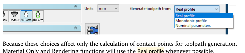
Figure 1 - The Mill tool list includes the 3D Form tool type and profile calculation options.
Step 5 - Complete the Tool Definition
Enter the tool number, Tool ID, description, material, number of flutes, spindle direction, and other required tool data.
Assign the correct holder and enter the actual length out of holder or stickout used for the setup.
Choose the Generate toolpath from method that matches the manufacturer's programming data and the intended contact behavior. Use Real profile when the actual imported shape must drive contact calculation unless a verified monotonic or nominal workflow is required.
Review Spline Machining Tolerance in DCD > Machining Preferences when the source shape contains free-form surfaces; both 2D and 3D Form tools use this setting.
Expected Result
The 3D Form tool has complete programming, holder, and identification data and is ready for a controlled test operation.
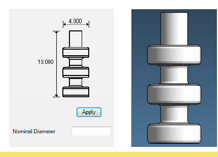
Figure 2 - Tool Creation preview and rendered form-tool example.
Step 6 - Create and Verify a Test Operation
Assign the 3D Form tool to a supported milling process and create a simple test operation using known stock and depth values.
Regenerate the operation and inspect the tool-center path, contact area, cutting side, entry, exit, and clearance moves.
Run Cut Part Rendering and Machine Simulation as appropriate. Check the cutter, shank, holder, part, stock, fixtures, and all inter-operation motion.
Compare the simulated result with the manufacturer's tool dimensions and intended cut. Review the posted coordinates, compensation method, tool length, spindle speed, and feedrate.
Complete the shop's normal prove-out procedure before releasing the tool for production.
Expected Result
The test operation uses the imported tool shape as intended, simulation shows the correct cutter and clearances, and the reviewed NC output agrees with the approved setup.
Profile Calculation Options
The Generate toolpath from choice changes how GibbsCAM calculates contact points for a Mill 3D Form tool. Select the method deliberately and validate the resulting path.
Best Practices
Use a standard GibbsCAM tool type when it represents the cutter accurately; use a 3D Form tool only when the custom revolved shape is needed.
Retain the original supplier file and keep a separate preparation workgroup so the imported body can be rebuilt if it is moved or united incorrectly.
Union only the bodies that define the cutter. Model the holder separately so stickout and holder-collision checks remain clear.
Position the tool using measured body extents and the original coordinate system rather than dragging it by eye.
Treat a non-monotonic warning as a verification checkpoint. Inspect the full profile, rapid moves, shank clearance, and the selected contact model.
Use realistic holder and stickout values and verify the assembly in both Cut Part Rendering and Machine Simulation when available.
Recheck the tool definition whenever the supplier revises the cutter model, inserts, holder, or programming dimensions.
Video Tutorial

Watch the CAMCO video: GibbsCAM Tech Tip: Importing a 3D Tool.
Troubleshooting
Problem: The tool imports at the wrong size.
Possible Causes
The supplier file uses different units from the GibbsCAM part.
The file format does not communicate units reliably, or the wrong import units were selected.
Resolution
Compare a known tool dimension with the manufacturer's drawing. Reimport with the correct units or apply a verified uniform scale before uniting and positioning the bodies.
Problem: Apply does not create the 3D Form tool.
Possible Causes
More than one body is still selected or the cutter components were not united into a single solid.
The selected body is a facet or surface model rather than a suitable solid.
The body is not centered about the X axis or the wrong item is selected.
Resolution
Isolate the cutter, unite its required solid components, verify that one solid body is selected, center it about the X axis, and apply it to a new 3D Form tool.
Problem: The imported tool is offset, inverted, or uses the wrong touch-off point.
Possible Causes
The model was not oriented to the required axis.
The minimum Z value was not translated to Z0, or the translation sign was reversed.
The manufacturer uses a different reference point than the one assumed during preparation.
Resolution
Confirm the manufacturer's programmed reference, orient the tool centerline to the X axis, query the body extents again, and translate the intended tool bottom to Z0. Recreate the tool after correcting the source body.
Problem: GibbsCAM reports that the tool is not monotonic in Z.
Possible Causes
The cutter widens after narrowing or contains an undercut profile.
An insert, shank feature, or unrelated solid component changes the radial profile.
Resolution
Compare the rendered tool with the supplier model and inspect the complete test toolpath. Use Real profile when the actual shape must control contact, or use a verified Monotonic profile or Nominal parameters workflow only when it matches the manufacturer's programming method.
Problem: The tool renders correctly but the calculated path or posted motion is unexpected.
Possible Causes
The Generate toolpath from method does not match the intended programming model.
The operation depth, stock, compensation, holder, or tool-offset data is incorrect.
A post-applied conversion or limit changes the output after internal toolpath calculation.
Resolution
Review the profile calculation option, operation inputs, tool and holder data, compensation method, and post requirements. Regenerate and simulate the operation, then inspect the NC output before machine prove-out.
Additional Information
GibbsCAM 2026 Mill documentation states that a 3D Form tool is created from a solid revolved shape selected from the workspace or Body Bag and that the solid must be centered about the X axis. The CAMCO video demonstrates importing a cutter body with separate inserts, uniting the components, using Shrink Wrap to find the bottom Z, translating that bottom to Z0, selecting 3D Form, and applying the solid.
The dimensions and facing-operation values shown in the video belong to its example. Use the actual stock, tool, holder, work offset, and operation values for the production job. Material Only and rendering use the real profile whenever possible, even when a different contact model is selected for toolpath generation.
Related Articles
- Form Tools Best Practices
- How to Create and Use 2D Form Tools
- How to Import CAD Files and CAD Compatibilities
- Recommended Simulation Settings
Explore More from CAMCO
Visit the CAMCO website to learn more about:
Keywords
GibbsCAM, Importing a 3D Tool, 3D Form Tool, Custom Tool, Solid Tool Model, Supplier Tool Model, Solid Model Union, Shrink Wrap, Tool Origin, Tool Bottom Z0, X Axis, Real Profile, Monotonic Profile, Nominal Parameters, Tool Simulation