
Summary
Polar & Cylindrical Milling is a GibbsCAM add-on that creates wrapped milling toolpath with continuous rotary-axis interpolation. Depending on the machine configuration, the wrapped motion is programmed about the A axis, B axis, or the C axis of a Mill/Turn machine.
This article explains how to distinguish indexed Position milling from continuous Polar & Cylindrical Milling, prepare flat or radial geometry, configure the Rotate tab, set safe rotary clearances, generate and simulate the operation, and optionally create cylindrical milling toolpath from Profiler Slice Cylinder profiles.
Table of Contents
- Before You Begin
- Position vs. Polar & Cylindrical Milling
- Procedure
- Best Practices
- Troubleshooting
- Related Articles
Before You Begin
Confirm that the GibbsCAM license includes the Polar & Cylindrical Milling option.
Select an MDD that defines the required rotary axis and matches the physical machine: commonly A for a vertical 4-axis mill, B for a horizontal 4-axis mill, or C for Mill/Turn.
Confirm that the post processor supports the required rotary or cylindrical interpolation mode for the target control.
Verify the rotary-axis centerline, stock, part position, fixtures, tool orientation, and machining coordinate systems.
Use geometry and process values that correspond to the actual part radius or diameter and the intended rotary axis.
Model the complete rotating envelope, including fixtures and workholding, before setting clearance planes.
Save a working copy of the part before changing workgroup wrapping, coordinate systems, or existing rotary operations.
Important: The Polar & Cylindrical Milling option controls continuous rotary interpolation. The Wrapped workgroup setting and Wrap Geometry or Wrap WGs command control how geometry is displayed and entered; they do not by themselves make the operation a wrapped toolpath.
Position vs. Polar & Cylindrical Milling
Procedure
Step 1 - Verify the Machine, License, and Post
Open the GibbsCAM part and select the MDD that represents the machine and rotary-axis configuration.
Confirm that the intended milling process includes a Rotate tab and that Polar & Cylindrical Milling is available as a rotation choice.
Verify that the machine assembly, rotary centerline, axis direction, and axis limits correspond to the physical machine.
Confirm with CAMCO or the shop's post administrator that the selected post supports the intended rotary or cylindrical interpolation output.
Expected Result
The part uses a rotary-capable machine definition and a compatible post, and the Polar & Cylindrical Milling selection is available.
Step 2 - Prepare the Machining Coordinate System
Display the coordinate-system grid and axis markers so the active plane and positive depth direction are visible.
Create or select the machining coordinate system that gives the tool the intended approach direction. GibbsCAM generates the operation along the positive depth axis of the selected machining CS.
Verify the rotary-axis centerline and the part radius or diameter relative to the selected coordinate system.
For Mill/Turn OD work, confirm the C0 orientation and the standard YZ machining relationship before generating a rotated or wrapped operation.
Expected Result
The machining coordinate system, rotary centerline, and part radius agree with the physical setup.
Step 3 - Create Flat Geometry or Enable Radial Geometry
Create or select the geometry that defines the cut shape. The geometry may remain flat; it does not have to be displayed as wrapped for Polar & Cylindrical Milling to create wrapped toolpath.
To work in radial mode, open Workgroup Info and select Wrapped for the geometry workgroup.
Turn on Modify > Wrap or the Wrap WGs button in the floating toolbar to display the wrapped workgroup radially.
When entering coordinates in radial mode, use the axis labels shown for the active machine configuration: commonly X, A, R for A-axis work; B, Y, R for B-axis work; or C, Z, R for Mill/Turn.
Confirm that the geometry lies at the intended radius or diameter and wraps in the correct angular direction.
Expected Result
The cut geometry is correctly located and may be viewed either flat or radially without changing the resulting wrapped toolpath.
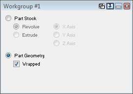
Figure 1 - Select Wrapped in Workgroup Info to place the workgroup in radial mode.
Step 4 - Create and Configure the Milling Process
Create the required milling process, such as Contour, Pocket, or another process supported by the machine and operation.
Select the tool and enter the required feature, depth, entry and exit, feeds, speeds, CRC, containment, and process-specific values.
Select the flat or wrapped geometry that defines the cut shape.
Open the Rotate tab and choose the intended machining coordinate system from Mach. CS.
Step 5 - Enable Polar & Cylindrical Milling
On the Rotate tab, select Polar & Cylindrical Milling instead of Position.
If the operation must repeat around the part, enter the number of additional repeats and the incremental rotary angle. Use zero repeats when no duplication is required.
Review any At-Singularity Starting Alignment choices displayed for the machine. Available choices depend on the operation and MDD; a raw Rotary Axis Angle is not available when Polar & Cylindrical Milling determines the start from the toolpath position.
Confirm that the selected rotary axis and positive direction match the intended wrap direction before generating the operation.
Expected Result
The process is configured for continuous rotary interpolation rather than a fixed indexed position.
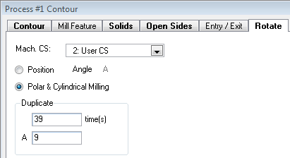
Figure 2 - Polar & Cylindrical Milling selected on the Rotate tab.
Step 6 - Set Safe Rotary Clearance
Set the document master clearance plane beyond the complete rotating envelope of the part and workholding.
Set the operation Entry Clearance as required for the cut and set the Exit Clearance high enough to clear every edge of the rotating part, fixture, jaws, and clamps before any rotary move.
Pay particular attention to operations without a tool change. In those cases, the tool may retract only to the Exit Clearance Plane before rotary positioning or transition moves.
As a geometry check on a vertical rotary setup, estimate the center-to-edge distance with sqrt(Y^2 + Z^2). For a horizontal setup, use sqrt(X^2 + Z^2). Round up and add the shop-approved safety margin; include fixtures and toolholder clearance separately.
Expected Result
The tool retracts outside the complete rotating envelope before indexed, wrapped, or inter-operation rotary motion.
Step 7 - Generate and Verify the Operation
Create or recalculate the operation and inspect the toolpath from multiple views.
Confirm that the rotary axis moves continuously and that the toolpath follows the intended cylindrical location, direction, and depth.
Run Op Simulation or Machine Simulation with the part, stock, fixtures, tool, holder, and machine components visible. Enable collision and program-error feedback for final verification.
If the rendered surface looks coarse, slow the simulation to tighten its angular display tolerance. GibbsCAM documentation notes that this changes rendering quality but does not change the output toolpath.
Review the posted program for the expected rotary or cylindrical interpolation mode, axis direction, start position, feed behavior, and safe clearance moves before releasing the program.
Expected Result
The operation uses continuous rotary interpolation, clears the rotating setup, and produces posted output appropriate for the machine and control.
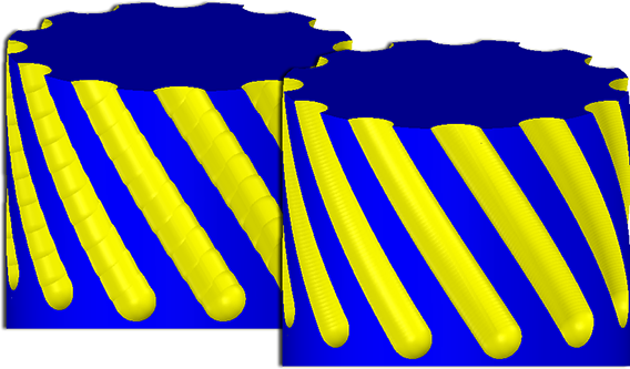
Figure 3 - Slow and fast simulation speeds can show different angular rendering tolerances.
Step 8 - Optional: Create Cylindrical Milling from Solid Profiles
Activate the coordinate system whose depth axis should define the Profiler Slice Cylinder axis.
Use Profiler in Slice Cylinder mode to select the required cylindrical profile from the solid.
Choose the appropriate machining coordinate system in the process. On a C-axis Mill/Turn example, the active XY plane can define the slice cylinder while the YZ plane is used as the machining CS.
Select one closed wrapped profile to machine a cylindrical boss or pocket, or select two loops that circumscribe the part to machine a groove or ring.
Use an appropriately sized tool. Cylindrical Milling toolpath from these profiles is analytic and tool-on-center, but it is not gouge-checked against the solid.
When close fidelity to the solid is more important than compact analytic cylindrical output, evaluate a supported 5-Axis Rotary strategy and verify the longer segmented toolpath.
Expected Result
The selected cylindrical profile produces the intended analytic wrapped boss, pocket, groove, or ring toolpath.
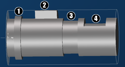
Figure 4 - Cylindrical profiles can define a ring, boss, groove, or pocket.
Expected Result
The operation uses continuous A-, B-, or C-axis interpolation and wraps the selected milling toolpath around the intended cylinder. Flat or radial geometry is interpreted at the correct radius, the tool retracts beyond the rotating envelope, simulation completes without unresolved collisions, and the posted program uses the output mode approved for the machine and control.
Best Practices
Use Position for fixed-angle indexing and Polar & Cylindrical Milling only when continuous rotary interpolation is required.
Keep the coordinate-system grid and axis markers visible while setting up rotary work.
Name wrapped workgroups and machining coordinate systems by axis, radius, setup, and purpose.
Verify radius versus diameter input whenever radial geometry appears at the wrong size or depth.
Use zero repeats unless the toolpath must be duplicated around the rotary axis.
Set Exit Clearance above the full rotating envelope, especially when no tool change occurs between operations.
Simulate the complete sequence, including entry, exit, repeats, and moves between operations, with fixtures and the holder visible.
Do not judge posted accuracy from coarse simulation alone; rendering angular tolerance changes with playback speed while output remains unaffected.
Prove out new rotary or cylindrical interpolation programs according to shop procedure and confirm the post, control mode, feed interpretation, and axis sign before production.
Troubleshooting
Problem: Polar & Cylindrical Milling is not available on the Rotate tab.
Possible Causes
The Polar & Cylindrical Milling option is not included on the license.
The selected MDD does not define a compatible A, B, or C rotary axis.
The active process, interface level, or product configuration does not expose the required rotary function.
Resolution
Verify the GibbsCAM license and select the correct rotary-capable MDD. Reopen a supported milling process and check the Rotate tab. If the option remains unavailable, confirm the required product and licensing configuration with CAMCO.
Problem: The operation indexes to one angle instead of creating continuous wrapped motion.
Possible Causes
Position is selected instead of Polar & Cylindrical Milling.
The wrong process or previously generated operation is being inspected.
The post or machine definition is not configured for the intended interpolation mode.
Resolution
Select Polar & Cylindrical Milling on the Rotate tab, regenerate the operation, and confirm continuous rotary motion in simulation. Verify the MDD and post before reviewing the posted output.
Problem: The geometry stays flat or does not display around the cylinder.
Possible Causes
Wrapped is not selected in Workgroup Info.
The Wrap Geometry or Wrap WGs display command is turned off.
A different workgroup is active or visible.
Resolution
Enable Wrapped for the correct workgroup and turn on Modify > Wrap or Wrap WGs. Remember that flat display does not prevent Polar & Cylindrical Milling from creating wrapped toolpath if the operation is configured correctly.
Problem: The toolpath wraps in the wrong direction, at the wrong radius, or at the wrong location.
Possible Causes
The machining coordinate system, rotary centerline, axis sign, or C0 orientation is incorrect.
Radius and diameter values were confused.
The geometry was created in the wrong plane or at the wrong radial depth.
Resolution
Verify the axis markers, machining CS, rotary centerline, positive direction, and C0 orientation. Confirm whether the active dialogs expect radius or diameter, correct the geometry or process values, and regenerate the operation.
Problem: The tool or holder collides during rotary motion.
Possible Causes
The master, entry, or exit clearance plane is inside the rotating envelope.
Fixture, jaw, clamp, holder, or machine-component geometry is missing or positioned incorrectly.
A move between operations was not reviewed with the complete setup visible.
Resolution
Raise the applicable clearance planes beyond the complete rotating envelope, correct the setup models, regenerate the affected operations, and simulate the full sequence with collision checking enabled.
Problem: The cylindrical-profile toolpath gouges or does not match the solid closely.
Possible Causes
Cylindrical Milling from Slice Cylinder profiles is not gouge-checked against the solid.
The tool is too large for the radial feature while the analytic toolpath remains tool-on-center.
The job requires off-center tool orientation or closer solid fidelity than analytic cylindrical interpolation provides.
Resolution
Use an appropriately sized tool and inspect the result carefully. If the required surface cannot be protected with analytic tool-on-center motion, evaluate a supported 5-Axis Rotary strategy and verify its segmented toolpath and posted output.
Problem: The simulated cylindrical surface looks faceted or coarse.
Possible Causes
Simulation playback is running fast and using a looser angular display tolerance.
The simulation or display settings favor performance over visual detail.
Resolution
Slow the simulation or use more accurate display settings for final visual review. The official documentation states that this rendering difference does not affect the output toolpath.
Additional Information
The GibbsCAM 2026 Mill documentation defines Polar & Cylindrical Milling as continuous A- or B-axis rotary interpolation for milling. The Mill/Turn guide applies the same concept to continuous C-axis motion and notes that the selected cut geometry may be flat or wrapped without changing the resulting Polar & Cylindrical toolpath.
Profiler Slice Cylinder toolpath is true analytic wrapped toolpath made from lines and arcs and can be output in cylindrical interpolation mode when the post and control support it. Because it is not gouge-checked against the solid and holds the tool on-center, tool size and verification are critical.
Related Articles
- How To Wrap/Unwrap a Workgroup
- Recommended Simulation Settings
- How to Set Fixture Avoidance
- Understanding CRC Types
Explore More from CAMCO
Visit the CAMCO website to learn more about:
Keywords
GibbsCAM, Polar Milling, Cylindrical Milling, Polar and Cylindrical Milling, Rotary Milling, Rotary Interpolation, Wrapped Toolpath, Wrapped Geometry, Radial Geometry, Wrap WGs, Workgroup Info, A Axis, B Axis, C Axis, Mill Turn, Rotate Tab, Position Milling, Machining Coordinate System, Rotary Clearance, Slice Cylinder, Cylindrical Profile, Ring, Boss, Groove, Pocket