
Summary
An open shape is a connected chain of geometry whose two ends do not join to form a fully enclosed boundary. GibbsCAM can contour an open shape on the left side, right side, or tool centerline while also controlling where the toolpath begins and ends beyond the geometry.
This article explains the two supported ways to control the cut side: position the machining marker circles on the selected geometry, or suppress markers in the Offset tab and choose Centerline or an Offset Direction. It also covers start and end extensions, shape direction, entry and exit moves, verification, and common troubleshooting steps.
Table of Contents
- Before You Begin
- Choose How GibbsCAM Determines the Cut Side
- Procedure
- Best Practices
- Troubleshooting
- Related Articles
Before You Begin
Open the GibbsCAM part and confirm that the correct machine, tool, stock, coordinate system, and workgroup are active.
Identify the complete open chain and confirm that its two intended endpoints do not connect to form a closed loop.
Inspect the chain for gaps, overlaps, duplicate entities, tiny segments, or unintended branches that could change selection behavior.
Confirm which physical side of the geometry must be cut and whether the operation must be climb, conventional, or centerline machining.
Verify the tool diameter, stock allowance, depth, CRC method, entry and exit clearance, and required start or end extension distances.
Save a working copy of the part before modifying geometry, markers, or an existing proven operation.
Plan to simulate the complete operation and review the posted code before running the program on the machine.
Important: Left and right are determined from the open shape's direction. GibbsCAM may reverse the displayed Climb and Conventional left/right labels when the spindle direction is reversed, so verify the actual toolpath rather than relying on the label alone.
Choose How GibbsCAM Determines the Cut Side
Procedure
Step 1 - Inspect and Orient the Open Shape
Display the geometry and select each entity in the intended chain to confirm that the shape is continuous from one endpoint to the other.
Verify that the two endpoints remain separate. Repair accidental gaps within the chain, but do not connect the final endpoints when the feature is intended to remain open.
Determine the chain's start-to-end direction. If only one end terminator is selected, GibbsCAM treats that terminator as the start point regardless of the shape's innate direction.
Confirm the intended tool side while looking along the shape direction. This establishes what left and right mean for the operation.
Expected Result
The selected chain is continuous but not closed, has the intended direction, and contains no duplicate or unwanted entities.
Step 2 - Create the Contour Process
Create or open a Mill Contour process and select the correct tool.
Set the feature depth, Z depths, stock allowance, feeds, speeds, clearance, and any process-specific options required for the cut.
Set CRC and the entry and exit moves according to the approved post, control, and shop procedure.
Close or move the process dialog as needed so the open geometry can be selected clearly.
Step 3 - Select the Open Shape
Select one connected open chain as the cut shape.
If machining markers are enabled, confirm that the start and end markers appear on the correct endpoints and that the intended portion of the chain is highlighted as the cut shape.
Place the tip of each marker arrowhead directly on a line, arc, circle, or point. To move a marker, click and hold it, drag it to the desired location, and release it.
For precise start or end placement, create a point at the desired location and snap the point marker to it.
Expected Result
GibbsCAM recognizes one open cut shape with the correct start point, end point, and chain direction.
Step 4 - Method A: Control the Cut with Machining Markers
Open the process Offset tab and keep Always use markers for single shapes selected.
Return to the selected geometry and use the machining marker circles to choose the left side, right side, or centerline of the open shape.
Use the direction arrow to set the direction of travel along the shape.
Move the start and end feature or point markers when only part of the chain should be machined or when the path must begin or end beyond the geometry.
Reopen the process and confirm that the marker placement produces the intended climb, conventional, or centerline result.
Expected Result
The marker circles and arrows define the intended cut side, direction, and start and end locations.
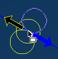
Figure 1 - Machining Markers used to indicate cutting side and direction on selected geometry.
Step 5 - Method B: Control the Cut from the Offset Tab
Open the Contour process and select the Offset tab.
Clear Always use markers for single shapes to suppress machining markers for the single selected shape.
To machine without side offset, select Centerline. This disables incompatible controls such as Climb, Conventional, and closed-shape inside or outside choices.
To offset the cutter, select Offset, then choose Climb (Left) or Conventional (Right) for the open shape.
If the spindle direction is reversed, use the labels shown in the active dialog; GibbsCAM can display Climb (Right) and Conventional (Left) instead.
Confirm that the selected direction places the cutter on the physical side required by the print and setup.
Expected Result
The Offset tab determines the open-shape side and direction without relying on displayed machining markers.
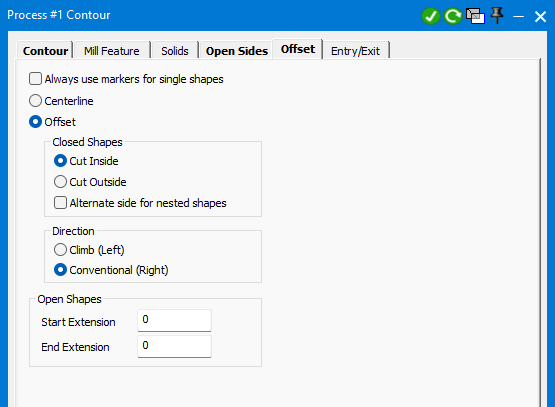
Figure 2 - Clear Always use markers for single shapes to select Centerline or an Offset Direction in the Offset tab.
Step 6 - Set Start and End Extensions
In the Open Shapes section of the Offset tab, enter the required Start Extension and End Extension values.
Use a positive extension when the toolpath must begin before the geometry or continue beyond it so the cutter can enter or exit completely off the feature.
Verify which endpoint GibbsCAM treats as the start. Reversing the shape direction also reverses which end receives the Start Extension and End Extension values.
Review any Overlap value on the Contour tab. When applicable, the open-shape Start and End Extension values are used instead of Overlap to preserve marker-based behavior.
Confirm that extensions do not drive the tool into clamps, stock, fixtures, or adjacent features.
Expected Result
The toolpath begins and ends at the intended distances relative to the open geometry.
Step 7 - Generate, Simulate, and Post
Create or recalculate the operation and inspect the toolpath from multiple views.
Verify the cut side, centerline or offset behavior, direction, start point, end point, extensions, depth, and stock allowance.
Run Op Simulation or Machine Simulation with stock, fixtures, tool, and holder visible. Review entry, exit, clearance, and any off-part extension moves.
Post the operation and confirm the expected CRC commands, direction, coordinates, feedrate, and safe approach and retract blocks.
Prove out the operation according to shop procedure before releasing it for production.
Expected Result
The verified toolpath follows the open chain on the intended side or centerline and starts and ends at safe, predictable locations.
Expected Result
The Contour operation recognizes the selected geometry as an open shape and machines it on the chosen left side, right side, or centerline. The toolpath follows the intended direction, applies the required start and end extensions, uses safe entry and exit motion, and posts with the approved CRC behavior for the machine and control.
Best Practices
Use machining markers when the operator needs interactive control over a single shape's cut side, direction, and endpoints.
Use the Offset tab when the same left/right rule should be applied without repositioning markers for each single shape.
Keep the start-to-end direction visible and verify left or right from that direction before generating the operation.
Place marker arrowheads directly on the geometry and use construction points when an exact start or end coordinate is required.
Use Centerline only when the tool center is intended to follow the geometry; side-offset and direction controls are disabled in this mode.
Set Start Extension and End Extension large enough to clear the feature, but verify that the extended motion remains clear of stock and workholding.
Select one open chain at a time when marker control is required. Multiple selected shapes can suppress markers and default to centerline behavior.
Simulate entry, exit, extensions, and the complete sequence with the toolholder and fixtures visible.
Inspect the posted program and prove out any new CRC, direction, or extension strategy before production.
Troubleshooting
Problem: Machining markers do not appear after the open shape is selected.
Possible Causes
Always use markers for single shapes is cleared in the Offset tab.
More than one continuous shape is selected, so GibbsCAM suppresses markers and assumes centerline machining.
The Offset tab is not applicable to the selected body, Profiler workflow, or Contour process paired with a Pocket process.
Resolution
Select only one open chain and enable Always use markers for single shapes. If the Offset tab is unavailable or ignored for the current process type, use the controls supported by that workflow and verify the resulting path.
Problem: The cutter is on the wrong side of the open geometry.
Possible Causes
The machining marker circle is positioned on the opposite side.
Climb (Left) or Conventional (Right) does not match the selected shape direction.
The spindle direction is reversed, changing the left/right labels associated with climb and conventional cutting.
Resolution
Verify the chain's start-to-end direction, move the marker circle to the intended side, or select the correct Offset Direction. Regenerate and inspect the physical cutter position from multiple views.
Problem: Centerline, Climb, or Conventional controls are unavailable or ignored.
Possible Causes
Centerline is selected, which disables incompatible side-offset controls.
The selected machining item is a body, the Profiler is being used, or Contour is paired with Pocket, making the Offset tab inapplicable.
The process or selected input does not support the expected geometry-offset behavior.
Resolution
Select Offset to enable the direction controls for a supported geometry-based Contour process. If the Offset tab remains unbolded or ineffective, verify the selected machining input and process combination.
Problem: Start Extension and End Extension are applied to the wrong ends.
Possible Causes
The open shape direction is opposite the intended machining direction.
Only one end terminator is selected, so GibbsCAM treats it as the start point regardless of innate shape direction.
The start and end markers are reversed or placed on unintended features.
Resolution
Reverse the machining direction or reposition the start and end markers, then regenerate the operation. Confirm the start arrow and verify each extension from the intended endpoint.
Problem: The toolpath does not begin or end far enough off the feature.
Possible Causes
Start Extension or End Extension is zero or too small for the tool diameter and entry or exit move.
An Overlap value on the Contour tab was expected, but the open-shape extension values are taking precedence.
The entry or exit move returns the cutter toward the feature after the extension.
Resolution
Enter practical Start and End Extension distances, review the Contour overlap and Entry/Exit settings together, then simulate the complete motion with stock and fixtures visible.
Problem: The open shape chains incorrectly or includes unwanted geometry.
Possible Causes
The geometry contains a gap, overlap, duplicate entity, small segment, or branch.
The selected chain reaches an unintended connected feature.
Imported geometry is fragmented or does not share exact endpoints.
Resolution
Inspect and repair the geometry, remove duplicate or unwanted entities, and select the chain again. Use precise endpoints or recreate the affected geometry when necessary.
Problem: The posted compensation or finished size does not match the GibbsCAM display.
Possible Causes
The selected CRC type changes the coordinates or offset value expected by the control.
The control register, tool diameter, stock allowance, or compensation sign is incorrect.
The entry or exit move does not give the control enough distance to activate or cancel compensation.
Resolution
Confirm the part's CRC type, tool data, stock allowance, D register, entry and exit length, and posted G40/G41/G42 behavior. Correct the approved setting and re-prove the operation before production.
Additional Information
In GibbsCAM 2026, selecting Always use markers for single shapes preserves the behavior of earlier releases. Clearing the option suppresses machining markers and lets the Offset tab control Centerline or the open-shape offset direction.
The Offset tab can hold settings for closed and open shapes at the same time. GibbsCAM applies the applicable controls to each selected shape type. For open shapes, Start Extension and End Extension define the distance from the geometry endpoints to the toolpath endpoints and can be used instead of Contour overlap values when marker behavior requires it.
Source: GibbsCAM 2026 Mill documentation, Offset Tab for Contouring and Machining Markers sections.
Related Articles
- Understanding CRC Types
- Geometry Does Not Connect or Disconnect Properly
- Extracting Geometry from Solids
- Recommended Simulation Settings
Explore More from CAMCO
Visit the CAMCO website to learn more about:
Keywords
GibbsCAM, Open Shape, Open Geometry, Non-Closed Shape, Contour, Machining Markers, Marker Circles, Always Use Markers for Single Shapes, Offset Tab, Centerline, Climb Left, Conventional Right, Cut Direction, Shape Direction, Start Extension, End Extension, Entry Exit, CRC, Cutter Radius Compensation, Geometry Chain, Toolpath