
Summary
VoluMill determines where it needs to enter the material; GibbsCAM does not currently provide a way to assign a specific user-selected plunge point to a VoluMill operation. When a controlled entry hole is required, a Holes process can generate one at the location—or locations—selected by VoluMill.
Place a Holes (drilling) process immediately above the VoluMill process in the Process list, open the Holes process's Pre-Mill tab, and select Entry. Generate the combined processes with Do It. GibbsCAM creates the pre-drill operation before the VoluMill operation, and VoluMill uses the generated hole as its entry location.
Table of Contents
Before You Begin
Open the GibbsCAM part and save a backup copy before changing the process stack or operation depths.
Create and verify the VoluMill process, including its selected part geometry or solid, stock definition, tool, cut depths, and clearances.
Choose a drill suitable for the material, holder, machine, and required entry depth.
Confirm that the drill diameter is larger than the VoluMill tool diameter so the milling tool can enter the drilled hole with clearance.
Avoid an excessively oversized drill; a large entry hole can remove protected material or gouge the part.
Confirm that the drill can reach the required depth without exceeding flute length, tool length, holder clearance, or machine travel.
Plan to inspect the generated drilling and VoluMill operations in simulation and in the posted CNC program before machining.
Important: Pre-drilling does not let you choose the VoluMill entry point. VoluMill still calculates the required entry location. The Holes process drills at that calculated location so the VoluMill tool can enter through the hole.
How Pre-drill Works
Procedure
Step 1 - Prepare the VoluMill Process
Create or open the VoluMill process that requires a pre-drilled entry hole.
Select the intended part geometry or solid and verify the stock, floor, depth, open-side, and avoidance definitions.
Set the VoluMill tool, feeds, speeds, cut width, step depth, allowances, and entry-related parameters for the operation.
Generate the VoluMill operation once and inspect the area where VoluMill intends to begin cutting.
Expected Result
The VoluMill process is valid and provides the machining context GibbsCAM needs to calculate its preferred entry location.
Step 2 - Choose the Pre-drill Tool
Add or select a drill whose diameter is larger than the VoluMill tool diameter.
Use only the additional diameter needed to provide safe entry clearance; do not select an unnecessarily large drill.
Verify drill point geometry, flute length, tool length, holder clearance, spindle speed, feedrate, coolant, and cycle settings.
Confirm that the drill can reach the planned depth without colliding with the part, stock, fixture, or machine components.
Expected Result
A suitable drill is available to create an entry hole that clears the VoluMill tool without unnecessarily enlarging the opening.
Step 3 - Stack the Holes Process Above VoluMill
Create a Holes (drilling) process in the same Process list as the VoluMill process.
Place the Holes process immediately above the VoluMill process so it is the directly preceding process.
Assign the selected drill and the required drilling parameters to the Holes process.
Keep the Holes and VoluMill processes together when generating the operations. If no milling process follows the Holes process, Pre-Mill does not generate the intended result.
Expected Result
The process stack reads from top to bottom as Holes followed immediately by VoluMill.
Step 4 - Select Entry on the Pre-Mill Tab
Open the Holes process and select the Pre-Mill tab. The tab should be bold or otherwise operative when the following VoluMill process is present in the Process list.
Select Entry to generate a hole at each start point VoluMill requires.
Leave Corner off unless the operation also requires corner drilling; Entry and Corner selections generate separate operations.
Do not select or construct a manual XY point expecting it to override VoluMill's calculated entry location.
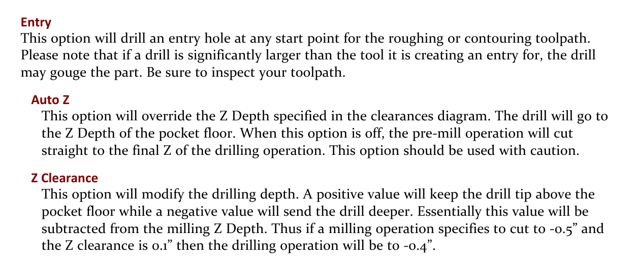
Figure 1 - Entry, Auto Z, and Z Clearance options on the Holes process Pre-Mill tab.
Expected Result
Entry is enabled in an operative Pre-Mill tab, allowing GibbsCAM to create drilling at VoluMill's calculated start location.
Step 5 - Set the Pre-drill Depth
Use Auto Z only when the drill should follow the milling pocket floor. Auto Z overrides the Z Depth specified in the Holes process clearances diagram.
When Auto Z is off, set the final Z of the drilling operation to the required entry-hole depth.
Set Z Clearance deliberately: a positive value keeps the drill tip above the milling floor, while a negative value sends it deeper. The value is subtracted from the milling Z depth.
Account for the drill-point shape so the usable full-diameter portion of the hole provides sufficient clearance for the VoluMill tool.
Check the final depth against the part floor, remaining stock, underlying features, fixture, and machine travel.
Expected Result
The entry hole reaches a safe, intentional depth and provides usable full-diameter clearance without drilling into protected material.
Step 6 - Generate the Combined Processes
With the Holes process directly above the VoluMill process, select the processes required for generation.
Select Do It to generate the operations.
Confirm that GibbsCAM creates the pre-drill operation before the VoluMill operation.
Inspect the generated hole location or locations. Their placement is determined by VoluMill and may change if the VoluMill toolpath or process inputs change.
If the VoluMill operation is later edited, regenerate the Holes and VoluMill processes together so the pre-drill location remains synchronized.
Expected Result
A drilling operation is generated at every entry location required by VoluMill and precedes the corresponding VoluMill operation.
Step 7 - Simulate and Verify
Run Op Simulation and verify the drill approach, cycle, retract, hole depth, and clearance from the part, stock, fixture, tool holder, and machine components.
Verify that the VoluMill tool enters through the drilled hole without cutting an unintended ramp or contacting uncut material at the entry.
Inspect every generated entry hole when the toolpath contains multiple start regions or depths.
Post the program and confirm the operation order, drilling cycle, Z depths, offsets, spindle commands, coolant, and VoluMill entry moves.
Resolve every discrepancy, then follow the shop's approved dry-run, single-block, and prove-out procedures before production machining.
Expected Result
The posted program drills each required entry hole first, and the VoluMill tool enters those holes with verified clearance and depth.
Expected Result
GibbsCAM generates a Holes operation immediately before the VoluMill operation. Each entry hole is positioned where VoluMill calculated a start point, has sufficient diameter and depth for the VoluMill tool, and is verified in simulation and the posted program before machining.
Best Practices
Keep the Holes process directly above the VoluMill process and regenerate them together after any toolpath change.
Remember that Entry pre-drilling follows VoluMill's calculated start point; it is not a manual entry-point selection feature.
Use a drill larger than the VoluMill tool, but avoid an excessive diameter that could gouge the part.
Account for the drill point when deciding whether the hole provides full-diameter clearance at the required entry depth.
Use Auto Z and Z Clearance only after confirming how they affect the final drilling depth.
Inspect every pre-drill operation when VoluMill creates multiple start regions or multiple depths.
Regenerate the process pair whenever part geometry, stock, tool diameter, depth, or VoluMill parameters change.
Verify the posted drilling cycle and operation order; post-processor behavior is not proven by graphics alone.
Retain a backup and document the pre-drill intent so future process edits do not separate or reorder the process pair.
Troubleshooting
Problem: The Pre-Mill tab is not bold, or selecting Entry produces no pre-drill operation.
Possible Causes
The Holes process is not combined with a following milling process.
The VoluMill process is above the Holes process or separated from it in the active process stack.
Only the Holes process was generated without the following VoluMill process context.
Resolution
Place the Holes process directly above the VoluMill process, keep both in the same active Process list, reopen the Holes process, select Entry, and generate the combined processes with Do It.
Problem: The entry hole is not at the manually selected point.
Possible Causes
VoluMill does not support assigning a specific user-selected plunge point.
The selected point or geometry is not used as an override for the calculated VoluMill entry location.
Resolution
Use the location generated by VoluMill's Entry pre-drill workflow. If that location is unacceptable, review the VoluMill process inputs and toolpath strategy; do not force the program to an unverified manual entry point.
Problem: VoluMill still ramps or plunges outside the drilled hole.
Possible Causes
The Holes and VoluMill processes were generated separately or are out of sequence.
The VoluMill process changed after the pre-drill operation was generated.
The drill is too small or too shallow to provide the required entry clearance.
The VoluMill toolpath contains more than one calculated start region, but not every entry hole was generated or reviewed.
Resolution
Restore the process order, verify Entry is selected, check drill diameter and depth, and regenerate both processes together. Inspect every start region and simulate the complete operation again.
Problem: The pre-drill operation gouges the part or removes too much material.
Possible Causes
The drill is significantly larger than the VoluMill tool.
The calculated entry location is close to a wall, island, feature, or protected surface.
The tool or part definition is incorrect or out of date.
Resolution
Stop and inspect the toolpath. Select a drill that provides the required clearance without excessive diameter, verify the part and tool definitions, regenerate the process pair, and confirm the result in simulation before posting.
Problem: The pre-drill hole is too shallow or too deep.
Possible Causes
Auto Z overrides the Holes process Z Depth and follows the milling pocket floor.
Z Clearance has the wrong sign or magnitude.
The final Z of the drilling operation is incorrect when Auto Z is off.
The drill-point length was not included when evaluating usable full-diameter depth.
Resolution
Review Auto Z, Z Clearance, the drilling operation's final Z, and the drill-point geometry. Correct the depth, regenerate both processes, and verify the actual hole profile against the part floor and protected features.
Problem: More than one pre-drill hole is generated.
Possible Causes
The VoluMill toolpath has multiple start points, disconnected regions, or depths that require separate entries.
Entry and Corner are both selected, creating separate drilling operations.
Resolution
Review each generated operation and start region. If corner drilling is not required, turn off Corner. Do not delete an Entry hole solely to reduce the operation count unless the revised VoluMill toolpath has been regenerated and fully verified.
Additional Information
Entry versus Corner: Entry drills at roughing or contouring start points. Corner drills qualifying corners for finishing access. Selecting both options creates separate operations, so verify the purpose and tool for each.
Related Articles
- Feed Rate Calculation
- How to Machine Pockets from Outside In
- Recommended Simulation Settings
- How to Set Fixture Avoidance
Explore More from CAMCO
Visit the CAMCO website to learn more about:
Keywords
GibbsCAM, VoluMill, Pre-drill, Predrill, Pre-Mill, Entry Hole, Holes Process, Drilling Process, Entry, Auto Z, Z Clearance, Plunge Point, Start Point, Drill Diameter, Pocket Floor, Process List, Do It, Toolpath Verification